PLUG-IN CHARGE CONTROL SYSTEM, Diagnostic DTC:P0D4D-404
| DTC Code | DTC Name |
|---|---|
| P0D4D-404 | On-Board Charger Output Voltage Sensor Circuit Range / Performance |
DESCRIPTION
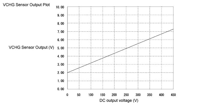
A VCHG sensor (DC output voltage sensor) is located inside the electric vehicle charger assembly. It detects output voltage to the DC high-voltage circuit and sends a signal to the plugin charge control ECU assembly. The plugin charge control ECU assembly monitors and detects errors in the VCHG sensor signal line.
The plugin charge control ECU assembly detects output power of the electric vehicle charger assembly based on signals from the VCHG sensor. At the same time, fusing of charge relay contacts is detected.
This DTC may also be stored if a short or open occurs in the high-voltage circuit (between the HV battery and electric vehicle charger assembly), or if the CHRG relay is stuck open. (In this case, DTC P02D0-422 (Charger Relay Stuck Open) is stored the next time plug-in charging is performed.)
| DTC No. | INF Code | DTC Detection Condition | Trouble Area |
|---|---|---|---|
| P0D4D | 404 | The difference between the battery voltage (VB) and charger output voltage sensor (VCHG) value is too large while the vehicle is being plug-in charged. |
|
| DTC No. | INF Code | Data List |
|---|---|---|
| P0D4D | 404 |
|
The following Data List items can be helpful when performing repairs:
-
VL-Voltage before Boosting (HYBRID CONTROL SYSTEM)
-
Power Resource VB (HYBRID CONTROL SYSTEM)
-
SMRB Control Status (HYBRID CONTROL SYSTEM)
-
SMRG Control Status (HYBRID CONTROL SYSTEM)
WIRING DIAGRAM
Refer to the wiring diagram for DTC P0D4E-416 Click here.
INSPECTION PROCEDURE
Tech Tips
After the repair, check that the Data List item "State of Charge (All Bat)" is 70% or less, then plug-in charge the vehicle for 20 seconds or more and check that DTCs are not output.
PROCEDURE
-
CHECK DTC OUTPUT (HYBRID CONTROL)
-
Connect the GTS to the DLC3.
-
Turn the power switch on (IG).
-
Enter the following menus: Powertrain / Hybrid Control / Trouble Codes.
-
Check if DTCs are output.
Result Result Proceed to Only P0D4D-404 is output or P0D4D-404 and DTCs other than the ones in the table below are also output. A Any of the following DTCs are also output. B DTC No. Relevant Diagnosis P1A61-123 Hybrid Battery Cell Low Voltage Stack "B" P1A64-123 Hybrid Battery Cell Low Voltage Stack "C" P1A67-123 Hybrid Battery Cell Low Voltage Stack "D" P31AB-123 Hybrid Battery Cell Low Voltage Tech Tips
P0D4D-404 may be set due to a malfunction which also causes DTCs in the preceding table to be set. In this case, first troubleshoot the output DTCs in the preceding table. Then, perform a test to attempt to reproduce the problems, and check that no DTCs are output.
-
Turn the power switch off.
B 
GO TO DTC CHART (HYBRID BATTERY SYSTEM) Click here
A 
-
-
CHECK DTC OUTPUT (HYBRID CONTROL)
-
Connect the GTS to the DLC3.
-
Turn the power switch on (IG).
-
Enter the following menus: Powertrain / Hybrid Control / Trouble Codes.
-
Check if DTCs are output.
Result Result Proceed to Only P0D4D-404 is output or P0D4D-404 and DTCs other than the ones in the table below are also output. A Any of the following DTCs are also output. B DTC No. Relevant Diagnosis P0A94-587 DC / DC Converter Performance P0ADC-226 Hybrid Battery Positive Contactor Control Circuit High P0AE0-228 Hybrid Battery Negative Contactor Control Circuit High P3004-131, 803 Power Cable Malfunction Tech Tips
P0D4D-404 may be output due to a malfunction which causes the DTCs in the table above to be output. In this case, first troubleshoot the output DTCs in the table above. Then, perform a reproduction test to check that no DTCs are output.
-
Turn the power switch off.
B
GO TO DTC CHART (HYBRID CONTROL SYSTEM) Click here
A
-
-
CHECK DTC OUTPUT (PLUG-IN CONTROL)
-
Connect the GTS to the DLC3.
-
Turn the power switch on (IG).
-
Enter the following menus: Powertrain / Plug-in Control / Trouble Codes.
-
Check if DTCs are output.
Result Result Proceed to Only P0D4D-404 is output or P0D4D-404 and DTCs other than the ones in the table below are also output. A Any of the following DTCs are also output. B DTC No. Relevant Diagnosis P0D20-422 Charger Relay Stuck Open P0D4D-405 On-Board Charger Output Voltage Sensor Circuit Range / Performance P0D4E-416 On-Board Charger Output Voltage Sensor Circuit Low P0D4F-417 On-Board Charger Output Voltage Sensor Circuit High P0D5C-847 Charging Power Malfunction Tech Tips
P0D4D-404 may be output due to a malfunction which causes the DTCs in the table above to be output. In this case, first troubleshoot the output DTCs in the table above. Then, perform a reproduction test to check that no DTCs are output.
-
Turn the power switch off.
B
GO TO DTC CHART (PLUG-IN CHARGE CONTROL SYSTEM) Click here
A
-
-
CHECK ELECTRIC VEHICLE CHARGER ASSEMBLY (VCHG SENSOR OUTPUT VOLTAGE)
CAUTION:
Be sure to wear insulated gloves.
-
Check that the service plug grip is not installed.
Note
After removing the service plug grip, do not turn the power switch on (READY), unless instructed by the repair manual because this may cause a malfunction.
-
Disconnect the z12 plugin charge control ECU assembly connector.
-
Connect the cable to the negative (-) auxiliary battery terminal.
-
Turn the power switch on (IG).
-
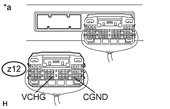
Text in Illustration *a Rear view of wire harness connector
(to Plugin Charge control ECU assembly)
Measure the voltage according to the value(s) in the table below.
Standard Voltage Tester Connection Condition Specified Condition z12-25 (VCHG) - z12-21 (CGND) Power switch on (IG) 1.5 to 2.5 V Tech Tips
Turning the power switch on (IG) with the plugin charge control ECU assembly connector disconnected causes other DTCs to be stored. Clear the DTCs after performing this inspection.
-
Turn the power switch off.
-
Disconnect the cable from the negative (-) auxiliary battery terminal.
-
Reconnect the z12 plugin charge control ECU assembly connector.
NG
REPLACE ELECTRIC VEHICLE CHARGER ASSEMBLY Click here
OK 
REPLACE PLUGIN CHARGE CONTROL ECU ASSEMBLY Click here
-