PLUG-IN CHARGE CONTROL SYSTEM, Diagnostic DTC:P0D3F-235, P0D40-236
| DTC Code | DTC Name |
|---|---|
| P0D3F-235 | On-Board Charger Input AC Voltage Sensor Circuit Low |
| P0D40-236 | On-Board Charger Input AC Voltage Sensor Circuit High |
DESCRIPTION
Refer to the description for DTC P0D3E-234 Click here.
| DTC No. | INF Code | DTC Detection Condition | Trouble Area |
|---|---|---|---|
| P0D3F | 235 | VAC sensor value remains less than 1.1 V for a certain period of time. |
|
| P0D40 | 236 | VAC sensor value remains more than 9.0 V for a certain period of time. |
| DTC No. | INF Code | Data List |
|---|---|---|
| P0D3F | 235 |
|
| P0D40 | 236 |
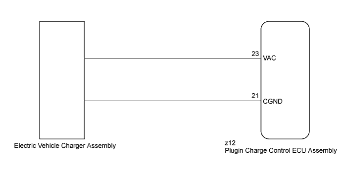
WIRING DIAGRAM
INSPECTION PROCEDURE
Tech Tips
After the repair, turn the power switch on (IG), wait for 10 seconds or more or plug-in charge the vehicle for at least 10 seconds, and check that DTCs are not output.
PROCEDURE
-
CHECK DTC OUTPUT (HYBRID CONTROL)
-
Connect the GTS to the DLC3.
-
Turn the power switch on (IG).
-
Enter the following menus: Powertrain / Plug-in Control / Trouble Codes.
-
Check if DTCs are output.
Result Result Proceed to Only P0D3F-235 or P0D40-236 is output or P0D3F-235, P0D40-236 and DTCs other than U019B-440 are also output. A U019B-440 is output. B -
Turn the power switch off.
B 
GO TO DTC CHART (U019B-440) Click here
A 
-
-
CHECK ELECTRIC VEHICLE CHARGER ASSEMBLY (VAC SENSOR OUTPUT VOLTAGE)
CAUTION:
Be sure to wear insulated gloves.
-
Check that the service plug grip is not installed.
Note
After removing the service plug grip, do not turn the power switch on (READY), unless instructed by the repair manual because this may cause a malfunction.
-
Disconnect the z12 plugin charge control ECU assembly connector.
-
Connect the cable to the negative (-) auxiliary battery terminal.
-
Turn the power switch on (IG).
-
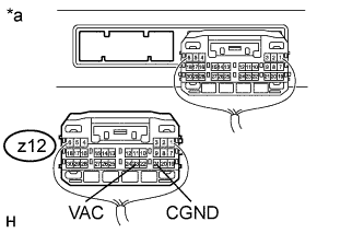
Text in Illustration *a Rear view of wire harness connector
(to Plugin Charge Control ECU Assembly)
Measure the voltage according to the value(s) in the table below.
Standard Voltage Tester Connection Condition Specified Condition z12-23 (VAC) - z12-21 (CGND) Power switch on (IG) 5.0 to 6.0 V Tech Tips
-
Turning the power switch on (IG) with the plugin charge control ECU assembly connector disconnected causes other DTCs to be stored. Clear the DTCs after performing this inspection.
-
The items "On-Board Charger Input Voltage" and "On-Board Charger Input Voltage Sensor Offset" in the freeze frame data and Data List are helpful for performing diagnosis.
-
Referring to the VAC Sensor Output Plot graph for this DTC, compare the Data List value and the VAC sensor output voltage.
-
-
Turn the power switch off.
-
Disconnect the cable from the negative (-) auxiliary battery terminal.
-
Reconnect the z12 plugin charge control ECU assembly connector.
NG
REPLACE ELECTRIC VEHICLE CHARGER ASSEMBLY Click here
OK 
REPLACE PLUGIN CHARGE CONTROL ECU ASSEMBLY Click here
-