PLUG-IN CHARGE CONTROL SYSTEM, Diagnostic DTC:P0D59-647
| DTC Code | DTC Name |
|---|---|
| P0D59-647 | Voltage High with On-Board Charger Connected |
DESCRIPTION
Refer to the description for DTC P0D58-646 Click here.
| DTC No. | INF Code | DTC Detection Condition | Trouble Area |
|---|---|---|---|
| P0D59 | 647 | PISW terminal voltage remains more than 4.7 V for a certain period of time. |
|
WIRING DIAGRAM
Refer to the wiring diagram for DTC P0D58-646 Click here.
INSPECTION PROCEDURE
Tech Tips
After the repair, plug-in charge the vehicle for at least 1 minute and check that the DTC is not output.
PROCEDURE
-
CHECK ELECTRIC VEHICLE CHARGER CABLE ASSEMBLY (CHECK FOR SHORT)
CAUTION:
Be sure to wear insulated gloves.
-
Plug in the electric vehicle charger cable assembly to a socket.
Tech Tips
Make sure not to connect it to the vehicle side charging inlet.
-
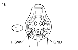
Text in Illustration *a Electric Vehicle Charger Cable Assembly
(Charging Connector Side)
Measure the voltage according to the value(s) in the table below.
Standard Voltage Tester Connection Condition Specified Condition t1-4 (PISW) - t1-3 (GND) Latch release button (PISW) is pressed Below 1 V t1-4 (PISW) - t1-3 (GND) Latch release button (PISW) is not pressed Below 1 V -
Disconnect the electric vehicle charger cable assembly from the socket.
NG 
REPLACE ELECTRIC VEHICLE CHARGER CABLE ASSEMBLY
OK 
-
-
CHECK CONNECTOR CONNECTION CONDITION (ELECTRIC VEHICLE CHARGER CABLE CONNECTOR)
-
Check the connector connection and contact pressure of the relevant terminals for the electric vehicle charger cable connector Click here.
OK The connector is connected securely and there are no contact pressure problems.
NG
CONNECT SECURELY
OK
-
-
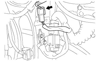
CHECK HARNESS AND CONNECTOR (CHARGING INLET - PLUGIN CHARGE CONTROL ECU ASSEMBLY)
-
Disconnect the S21 plugin charge control ECU assembly connector.
-
Turn the power switch on (IG).
-
Text in Illustration *a Electric Vehicle Charger Cable
(Charging Inlet Side)
Measure the voltage according to the value(s) in the table below.
Standard Voltage Tester Connection Condition Specified Condition t1-4 (PISW) - t1-3 (GND) Power switch on (IG) Below 1 V t1-4 (PISW) - Body ground Power switch on (IG) Below 1 V -
Turn the power switch off.
-
Reconnect the S21 plugin charge control ECU assembly connector.
NG 
CHECK ELECTRIC VEHICLE CHARGER CABLE (CHECK FOR SHORT) Click here
OK
-
-
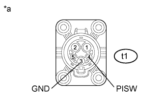
CHECK ELECTRIC VEHICLE CHARGER CABLE
-
Disconnect the St1 electric vehicle charger cable connector.
-
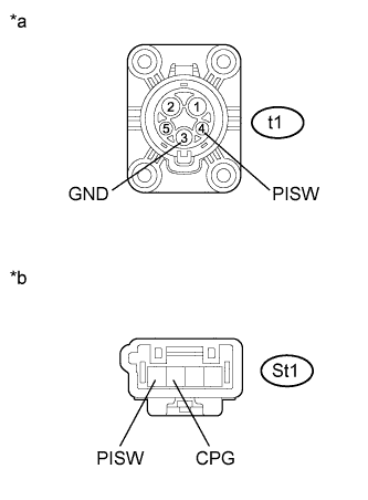
Text in Illustration *a Electric Vehicle Charger Cable
(Charging Inlet Side)
*b Component without harness connected
(Electric Vehicle Charger Cable)
Measure the resistance according to the value(s) in the table below.
Standard Resistance Tester Connection Condition Specified Condition t1-4(PISW) - t1-3(GND) Power switch off 2.3 to 3.0 kΩ t1-3(GND) - Body ground Power switch off Below 1 Ω t1-4(PISW) - St1-4(PISW) Power switch off Below 1 Ω t1-3(GND) - St1-3(CPG) Power switch off Below 1 Ω -
Reconnect the St1 electric vehicle charger cable connector.
NG
REPAIR OR REPLACE ELECTRIC VEHICLE CHARGER CABLE Click here
OK
-
-
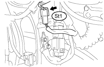
CHECK HARNESS AND CONNECTOR (ELECTRIC VEHICLE CHARGER - PLUGIN CHARGE CONTROL ECU ASSEMBLY)
-
Disconnect the St1 electric vehicle charger cable connector.
-
Disconnect the S31 plugin charge control ECU assembly connector.
-
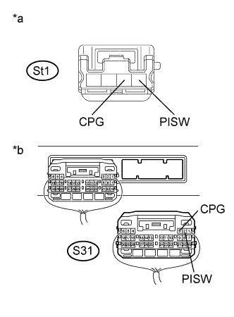
Text in Illustration *a Front view of wire harness connector
(to Electric Vehicle Charger Cable)
*b Rear view of wire harness connector
(to Plugin Charge Control ECU Assembly)
Measure the resistance according to the value(s) in the table below.
Standard Resistance Tester Connection Condition Specified Condition St1-4(PISW) - S31-2(PISW) Power switch off Below 1 Ω St1-3(CPG) - S31-3(CPG) Power switch off Below 1 Ω -
Reconnect the S31 plugin charge control ECU assembly connector.
-
Reconnect the St1 electric vehicle charger cable connector.
NG
REPAIR OR REPLACE HARNESS OR CONNECTOR
OK 
REPLACE PLUGIN CHARGE CONTROL ECU ASSEMBLY Click here
-
-
CHECK ELECTRIC VEHICLE CHARGER CABLE (CHECK FOR SHORT)
-
Disconnect the St1 electric vehicle charger cable connector.
-
Turn the power switch on (IG).
-
Text in Illustration *a Electric Vehicle Charger Cable
(Charging Inlet Side)
Measure the voltage according to the value(s) in the table below.
Standard Voltage Tester Connection Condition Specified Condition t1-4 (PISW) - t1-3(GND) Power switch on (IG) Below 1 V t1-4 (PISW) - Body ground Power switch on (IG) Below 1 V -
Turn the power switch off.
-
Reconnect the St1 electric vehicle charger cable connector.
NG
REPAIR OR REPLACE ELECTRIC VEHICLE CHARGER CABLE Click here
OK
REPAIR OR REPLACE HARNESS OR CONNECTOR
-