HYBRID CONTROL SYSTEM Pattern Select Switch Eco Mode Circuit
DESCRIPTION
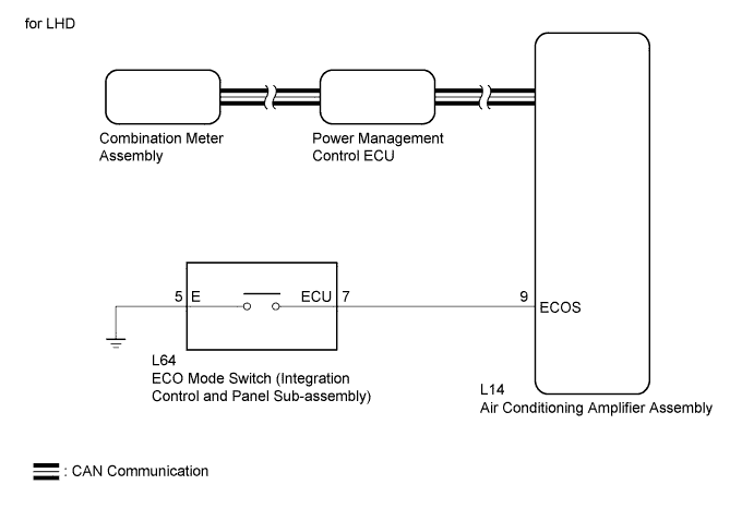
When selecting ECO drive mode, the ECO mode switch (integration control and panel sub-assembly) operation signal is sent to the air conditioning amplifier assembly. Following this, ECO drive mode control is activated for the heater and air conditioning system.
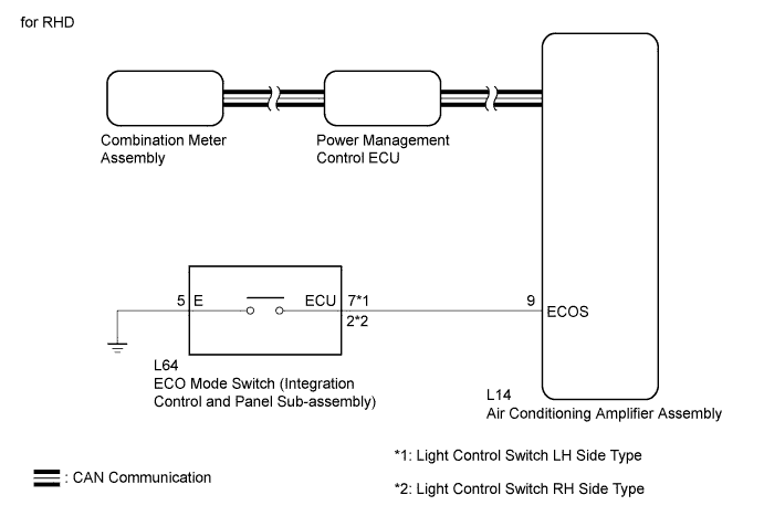
WIRING DIAGRAM
INSPECTION PROCEDURE
PROCEDURE
-
READ VALUE USING GTS (CAN BUS CHECK)
-
Connect the GTS to the DLC3.
-
Turn the power switch on (IG).
-
Enter the following menus: System Select / CAN Bus Check.
Result Result Proceed to All of the ECUs and sensors that are currently connected to the CAN communication system are displayed. A None of the ECUs and sensors that are currently connected to the CAN communication system are displayed, or some of them are not displayed. B -
Turn the power switch off.
B 
GO TO CAN COMMUNICATION SYSTEM Click here
A 
-
-
CHECK DTC OUTPUT (HEALTH CHECK)
-
Connect the GTS to the DLC3.
-
Turn the power switch on (IG).
-
Enter the following menus: System Select / Health Check.
-
Check DTCs.
Result Result Proceed to No DTCs are output. A DTCs are output. B -
Turn the power switch off.
B
GO TO DTC CHART
A
-
-
PERFORM ACTIVE TEST USING GTS (INDICAT. ECO MODE)
-
Connect the GTS to the DLC3.
-
Turn the power switch on (IG).
-
Enter the following menus: Body Electrical / Combination Meter / Active Test / Indicat. ECO Mode.
-
Perform the "Indicat. ECO MODE" Active Test.
OK The ECO MODE indicator lamp comes on or blinks. -
Turn the power switch off.
NG
REPLACE NO. 2 METER CIRCUIT PLATE Click here
OK
-
-
READ VALUE USING GTS (ECO MODE)
-
Connect the GTS to the DLC3.
-
Turn the power switch on (IG).
-
Enter the following menus: Powertrain / Hybrid Control / Data List / ECO Mode.
-
Read the value displayed on the GTS.
Tester Display Measurement Item/Range Normal Condition ECO Mode ECO drive mode transition availability/
ON or OFF
In ECO drive mode: ON Result Result Proceed to The GTS display changes according to the ECO mode switch (integration control and panel sub-assembly) operation. A The GTS display does not changes according to the ECO mode switch (integration control and panel sub-assembly) operation. B
B 
READ VALUE USING GTS (ECO SWITCH) Click here
A 
CHECK FOR INTERMITTENT PROBLEMS Click here
-
-
READ VALUE USING GTS (ECO SWITCH)
-
Connect the GTS to the DLC3.
-
Turn the power switch on (IG).
-
Enter the following menus: Body Electrical / Air Conditioning / Data List / ECO Switch.
-
Read the value displayed on the GTS.
Tester Display Measurement Item/Range Normal Condition ECO Switch ECO mode switch (integration control and panel sub-assembly) condition/
ON or OFF
ECO mode switch (integration control and panel sub-assembly) being pushed and held: ON
ECO mode switch (integration control and panel sub-assembly) not pushed: OFF
Result Result Proceed to The GTS display changes according to the ECO mode switch (integration control and panel sub-assembly) operation. A The GTS display does not changes according to the ECO mode switch (integration control and panel sub-assembly) operation. B
B
CHECK ECO MODE SWITCH (INTEGRATION CONTROL AND PANEL SUB-ASSEMBLY) Click here
A
REPLACE AIR CONDITIONING AMPLIFIER ASSEMBLY Click here
-
-
CHECK ECO MODE SWITCH (INTEGRATION CONTROL AND PANEL SUB-ASSEMBLY)
-
Remove the ECO mode switch (integration control and panel sub-assembly) Click here.
-
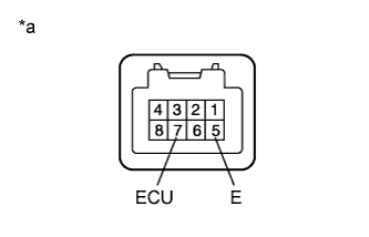
Text in Illustration *a Component without harness connected
(ECO Mode Switch (Integration Control and Panel Sub-assembly))
Measure the resistance according to the value(s) in the table below. (for LHD)
Standard Resistance Tester Connection Condition Specified Condition 7 (ECU) - 5 (E) ECO mode switch (integration control and panel sub-assembly) being pushed and held Below 1 Ω ECO mode switch (integration control and panel sub-assembly) not pushed 10 kΩ or higher -
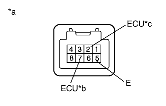
Text in Illustration *a Component without harness connected
(ECO Mode Switch (Integration Control and Panel Sub-assembly))
*b Light Control Switch LH Side Type *c Light Control Switch RH Side Type Measure the resistance according to the value(s) in the table below. (for RHD)
Standard Resistance Light Control Switch LH Side Type Tester Connection Condition Specified Condition 7 (ECU) - 5 (E) ECO mode switch (integration control and panel sub-assembly) being pushed and held Below 1 Ω ECO mode switch (integration control and panel sub-assembly) not pushed 10 kΩ or higher Standard Resistance Light Control Switch RH Side Type Tester Connection Condition Specified Condition 2 (ECU) - 5 (E) ECO mode switch (integration control and panel sub-assembly) being pushed and held Below 1 Ω ECO mode switch (integration control and panel sub-assembly) not pushed 10 kΩ or higher -
Install the ECO mode switch (integration control and panel sub-assembly).
NG
REPLACE ECO MODE SWITCH (INTEGRATION CONTROL AND PANEL SUB-ASSEMBLY) Click here
OK
-
-
CHECK HARNESS AND CONNECTOR (ECO MODE SWITCH (INTEGRATION CONTROL AND PANEL SUB-ASSEMBLY) - BODY GROUND)
-
Disconnect the L64 ECO mode switch (integration control and panel sub-assembly) connector.
-
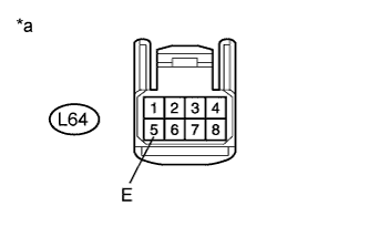
Text in Illustration *a Front view of wire harness connector
(to ECO Mode Switch (Integration Control and Panel Sub-assembly))
Measure the resistance according to the value(s) in the table below.
Standard Resistance Tester Connection Condition Specified Condition L64-5 (E) - Body ground Always Below 1 Ω -
Reconnect the L64 ECO mode switch (integration control and panel sub-assembly) connector.
NG
REPAIR OR REPLACE HARNESS OR CONNECTOR
OK
-
-
CHECK HARNESS AND CONNECTOR (AIR CONDITIONING AMPLIFIER ASSEMBLY - COMBINATION SWITCH)
-
Disconnect the L14 air conditioning amplifier assembly connector.
-
Disconnect the L64 ECO mode switch (integration control and panel sub-assembly) connector.
-
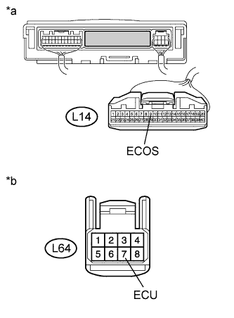
Text in Illustration *a Front view of wire harness connector
(to Air Conditioning Amplifier Assembly)
*b Front view of wire harness connector
(to ECO Mode Switch (Integration Control and Panel Sub-assembly))
Measure the resistance according to the value(s) in the table below. (for LHD)
Standard Resistance Tester Connection Condition Specified Condition L14-9 (ECOS) - L64-7 (ECU) Always Below 1 Ω L14-9 (ECOS) or L64-7 (ECU) - Body ground Always 10 kΩ or higher -
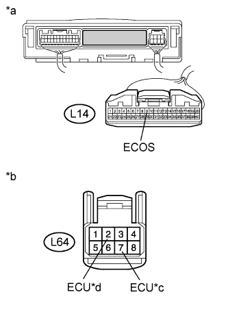
Text in Illustration *a Front view of wire harness connector
(to Air Conditioning Amplifier Assembly)
*b Front view of wire harness connector
(to ECO Mode Switch (Integration Control and Panel Sub-assembly))
*c Light Control Switch LH Side Type *d Light Control Switch RH Side Type Measure the resistance according to the value(s) in the table below. (for RHD)
Standard Resistance Light Control Switch LH Side Type Tester Connection Condition Specified Condition L14-9 (ECOS) - L64-7 (ECU) Always Below 1 Ω L14-9 (ECOS) or L64-7 (ECU) - Body ground Always 10 kΩ or higher Standard Resistance Light Control Switch RH Side Type Tester Connection Condition Specified Condition L14-9 (ECOS) - L64-2 (ECU) Always Below 1 Ω L14-9 (ECOS) or L64-2 (ECU) - Body ground Always 10 kΩ or higher -
Reconnect the L64 ECO mode switch (integration control and panel sub-assembly) connector.
-
Reconnect the L14 air conditioning amplifier assembly connector.
NG
REPAIR OR REPLACE HARNESS OR CONNECTOR
OK
REPLACE AIR CONDITIONING AMPLIFIER ASSEMBLY Click here
-