HYBRID CONTROL SYSTEM Pattern Select Switch EV City Mode Circuit
DESCRIPTION
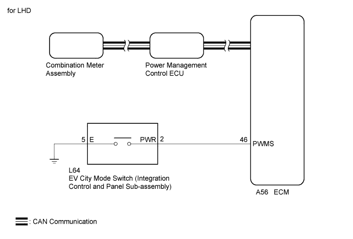
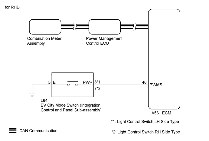
The EV city mode signal will be sent to the ECM when the EV city mode switch (integration control and panel sub-assembly) is operated. If the specified conditions are met, the system enters EV city mode and the vehicle will be driven using EV city mode. This signal is then transmitted from the ECM via CAN to the combination meter assembly to illuminate the EV city mode indicator light.
WIRING DIAGRAM
INSPECTION PROCEDURE
If any of the following conditions are not met, EV city mode may not be turned on or the mode may be cancelled. (A buzzer sounds to indicate that the transition to EV city mode is cancelled.)
| EV City Mode Entry Condition | Tester Display | Specified Condition |
|---|---|---|
| HV battery charge level | State of Charge (All Bat) | Approximately 23.4% or higher |
| Accelerator pedal position | Accelerator Degree | Approximately 90% or less |
| Engine coolant temperature | Engine Coolant Temp | -10°C (14°F) or higher |
| HV battery temperature | Temp of Batt TB1 to TB12 | -10°C (14°F) or higher |
| Vehicle speed (Varies depending on engine warm-up condition) |
Vehicle Spd | 85 km/h (53 mph) or less |
| Win | Charge Control Value | Below 0 kW |
| Wout | Discharge Control Value | 25 kW or higher |
| Defroster | - | OFF |
| Heater | - | OFF or ON (Engine off) |
| Cruise control | - | OFF |
PROCEDURE
-
ASK ABOUT VEHICLE CONDITION
-
Check if a buzzer sounded and a message was displayed on the multi-information display when attempting to enter EV city mode.
Result Result Proceed to No buzzer sounded and no message was displayed on multi-information display. A A buzzer sounded and a message was displayed on multi-information display. B Tech Tips
If a buzzer sounds and a message is displayed on multi-information display, one or more of the EV city mode entry conditions have not been met. Check that all of the EV city mode entry conditions have been met before pressing the EV city mode switch (integration control and panel sub-assembly).
B 
COMPLETED
A 
-
-
READ VALUE USING GTS (CAN BUS CHECK)
-
Connect the GTS to the DLC3.
-
Turn the power switch on (IG).
-
Enter the following menus: System Select / CAN Bus Check.
Result Result Proceed to All of the ECUs and sensors that are currently connected to the CAN communication system are displayed. A None of the ECUs and sensors that are currently connected to the CAN communication system are displayed, or some of them are not displayed. B -
Turn the power switch off.
B
GO TO CAN COMMUNICATION SYSTEM Click here
A
-
-
CHECK DTC OUTPUT (HEALTH CHECK)
-
Connect the GTS to the DLC3.
-
Turn the power switch on (IG).
-
Enter the following menus: System Select / Health Check.
-
Check DTCs.
Result Result Proceed to No DTCs are output. A DTCs are output. B -
Turn the power switch off.
B
GO TO DTC CHART
A
-
-
PERFORM ACTIVE TEST USING GTS (INDICAT. LAMP ECT PWR)
-
Connect the GTS to the DLC3.
-
Turn the power switch on (IG).
-
Enter the following menus: Body Electrical / Combination Meter / Active Test / Indicat. Lamp EV CITY.
-
Perform the "Indicat. Lamp ECT PWR" Active Test.
OK The EV city mode indicator light comes on or blinks. -
Turn the power switch off.
NG
REPLACE NO. 2 METER CIRCUIT PLATE Click here
OK
-
-
READ VALUE USING GTS (EV CITY MODE)
-
Connect the GTS to the DLC3.
-
Turn the power switch on (IG).
-
Enter the following menus: Powertrain / Hybrid Control / Data List / EV City Mode.
-
Read the value displayed on the GTS.
Tester Display Measurement Item/Range Normal Condition EV City Mode EV city mode transition availability/
ON or OFF
In EV city mode: ON Result Result Proceed to The GTS display changes according to the EV city mode switch (integration control and panel sub-assembly) operation. A The GTS display does not changes according to the EV city mode switch (integration control and panel sub-assembly) operation. B
B 
READ VALUE USING GTS (EV CITY MODE SWITCH) Click here
A 
CHECK FOR INTERMITTENT PROBLEMS Click here
-
-
READ VALUE USING GTS (EV CITY MODE SWITCH)
-
Connect the GTS to the DLC3.
-
Turn the power switch on (IG).
-
Enter the following menus: Powertrain / Engine / Data List / EV City Mode Switch.
-
Read the value displayed on the GTS.
Tester Display Measurement Item/Range Normal Condition EV City Mode Switch EV city mode switch (integration control and panel sub-assembly) condition/
ON or OFF
EV city mode switch (integration control and panel sub-assembly) being pushed and held: ON Result Result Proceed to The GTS display changes according to the EV city mode switch (integration control and panel sub-assembly) operation. A The GTS display does not changes according to the EV city mode switch (integration control and panel sub-assembly) operation. B
B
CHECK EV CITY MODE SWITCH (INTEGRATION CONTROL AND PANEL SUB-ASSEMBLY) Click here
A
REPLACE ECM Click here
-
-
CHECK EV CITY MODE SWITCH (INTEGRATION CONTROL AND PANEL SUB-ASSEMBLY)
-
Remove the EV city mode switch (integration control and panel sub-assembly) Click here.
-
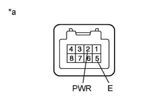
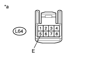
Text in Illustration *a Component without harness connected
(EV City Mode Switch (Integration Control and Panel Sub-assembly))
Measure the resistance according to the value(s) in the table below. (for LHD)
Standard Resistance Tester Connection Condition Specified Condition 2 (PWR) - 5 (E) EV city mode switch (integration control and panel sub-assembly) being pushed and held Below 1 Ω EV city mode switch (integration control and panel sub-assembly) not pushed 10 kΩ or higher -
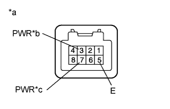
Text in Illustration *a Component without harness connected
(EV City Mode Switch (Integration Control and Panel Sub-assembly))
*b Light Control Switch LH Side Type *c Light Control Switch RH Side Type Measure the resistance according to the value(s) in the table below. (for RHD)
Standard Resistance Light Control Switch LH Side Type Tester Connection Condition Specified Condition 3 (PWR) - 5 (E) EV city mode switch (integration control and panel sub-assembly) being pushed and held Below 1 Ω EV city mode switch (integration control and panel sub-assembly) not pushed 10 kΩ or higher Standard Resistance Light Control Switch RH Side Type Tester Connection Condition Specified Condition 7 (PWR) - 5 (E) EV city mode switch (integration control and panel sub-assembly) being pushed and held Below 1 Ω EV city mode switch (integration control and panel sub-assembly) not pushed 10 kΩ or higher -
Install the EV city mode switch (integration control and panel sub-assembly).
NG
REPLACE EV CITY MODE SWITCH (INTEGRATION CONTROL AND PANEL SUB-ASSEMBLY) Click here
OK
-
-
CHECK HARNESS AND CONNECTOR (EV CITY MODE SWITCH (INTEGRATION CONTROL AND PANEL SUB-ASSEMBLY) - BODY GROUND)
-
Disconnect the L64 EV city mode switch (integration control and panel sub-assembly) connector.
-
Text in Illustration *a Front view of wire harness connector
(to EV City Mode Switch (Integration Control and Panel Sub-assembly))
Measure the resistance according to the value(s) in the table below.
Standard Resistance Tester Connection Condition Specified Condition L64-5 (E) - Body ground Always Below 1 Ω -
Reconnect the L64 EV city mode switch (integration control and panel sub-assembly) connector.
NG
REPAIR OR REPLACE HARNESS OR CONNECTOR
OK
-
-
CHECK HARNESS AND CONNECTOR (ECM - EV CITY MODE SWITCH (INTEGRATION CONTROL AND PANEL SUB-ASSEMBLY))
-
Disconnect the A56 ECM connector.
-
Disconnect the L64 EV city mode switch (integration control and panel sub-assembly) connector.
-
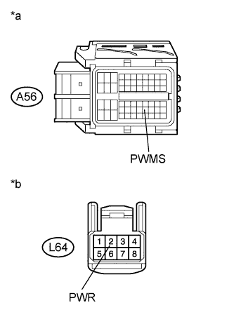
Text in Illustration *a Front view of wire harness connector
(to ECM)
*b Front view of wire harness connector
(to EV City Mode Switch (Integration Control and Panel Sub-assembly))
Measure the resistance according to the value(s) in the table below. (for LHD)
Standard Resistance Tester Connection Condition Specified Condition A56-46 (PWMS) - L64-2 (PWR) Always Below 1 Ω A56-46 (PWMS) or L64-2 (PWR) - Body ground Always 10 kΩ or higher -
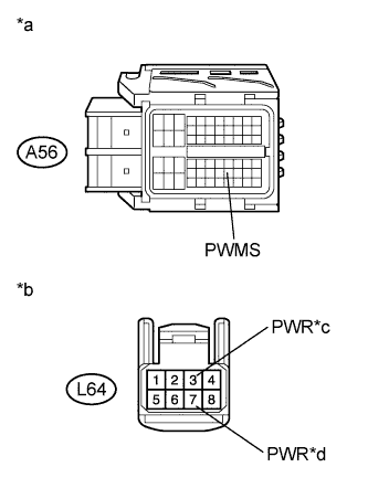
Text in Illustration *a Front view of wire harness connector
(to ECM)
*b Front view of wire harness connector
(to EV City Mode Switch (Integration Control and Panel Sub-assembly))
*c Light Control Switch LH Side Type *d Light Control Switch RH Side Type Measure the resistance according to the value(s) in the table below. (for RHD)
Standard Resistance Light Control Switch LH Side Type: Tester Connection Condition Specified Condition A56-46 (PWMS) - L64-3 (PWR) Always Below 1 Ω A56-46 (PWMS) or L64-3 (PWR) - Body ground Always 10 kΩ or higher Standard Resistance Light Control Switch RH Side Type: Tester Connection Condition Specified Condition A56-46 (PWMS) - L64-7 (PWR) Always Below 1 Ω A56-46 (PWMS) or L64-7 (PWR) - Body ground Always 10 kΩ or higher -
Reconnect the L64 EV city mode switch (integration control and panel sub-assembly) connector.
-
Reconnect the A56 ECM connector.
NG
REPAIR OR REPLACE HARNESS OR CONNECTOR
OK
REPLACE ECM Click here
-