HYBRID CONTROL SYSTEM, Diagnostic DTC:P3203-419
| DTC Code | DTC Name |
|---|---|
| P3203-419 | On-Board Charger Gate Circuit Stuck Closed |
DESCRIPTION
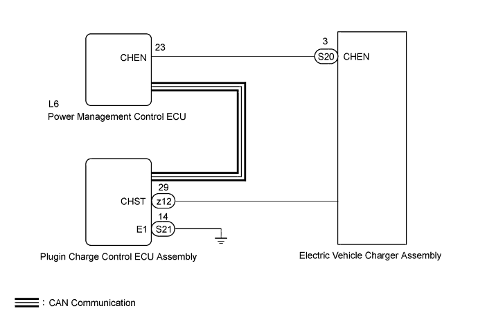
The power management control ECU sends a charger operation permission/stop signal (CHEN signal) to the electric vehicle charger assembly. It checks the charger gate shutoff function and stores a DTC when it is malfunctioning.
For details of plug-in charge, refer to the circuit description for DTC P0D5C-847 Click here.
For details of CHST signal, refer to the circuit description for DTC P0D67-844 Click here.
| DTC No. | INF Code | DTC Detection Condition | Trouble Area |
|---|---|---|---|
| P3203 | 419 | A certain period of time has elapsed with the charger operating even though the power management control ECU is sending the charger shutoff command. |
|
INSPECTION PROCEDURE
CAUTION:
-
Before inspecting the high-voltage system or disconnecting the low voltage connector of the inverter with converter assembly or electric vehicle charger assembly, turn the power switch off. Also, take safety precautions such as wearing insulated gloves and removing the service plug grip to prevent electrical shocks. After removing the service plug grip, put it in your pocket to prevent other technicians from accidentally reconnecting it while you are working on the high-voltage system.
-
After removing the service plug grip, wait for at least 10 minutes before touching any of the high-voltage connectors or terminals. After waiting for 10 minutes, check the voltage at the terminals in the inspection point in the inverter with converter assembly. The voltage should be 0 V before beginning work Click here.
Tech Tips
Waiting for at least 10 minutes is required to discharge the high-voltage capacitor inside the inverter with converter assembly and electric vehicle charger assembly.
Note
After turning the power switch off, waiting time may be required before disconnecting the cable from the negative (-) auxiliary battery terminal. Therefore, make sure to read the disconnecting the cable from the negative (-) auxiliary battery terminal notices before proceeding with work Click here.
Tech Tips
After the repair, check that the Data List item [State of Charge (All Bat)] is 70% or less, then plug-in charge the vehicle for 1 minute or more and check that DTCs are not output.
PROCEDURE
-
CHECK DTC OUTPUT (HYBRID CONTROL)
-
Connect the GTS to the DLC3.
-
Turn the power switch on (IG).
-
Enter the following menus: Powertrain / Hybrid Control / Trouble Codes.
-
Check if DTCs are output.
Result Result Proceed to Only P3203-419 is output or P3203-419 and DTCs other than U019B-440 are also output. A U019B-440 is also output. B Tech Tips
P3203-419 may be set due to a malfunction which also causes DTCs in the preceding table to be set. In this case, first troubleshoot the output DTCs in the preceding table. Then, perform a test to attempt to reproduce the problems, and check that no DTCs are output.
-
Turn the power switch off.
B 
GO TO DTC CHART (HYBRID CONTROL SYSTEM) Click here
A 
-
-
CHECK DTC OUTPUT (PLUG-IN CONTROL)
-
Connect the GTS to the DLC3.
-
Turn the power switch on (IG).
-
Enter the following menus: Powertrain / Plug-in Control / Trouble Codes.
-
Check if DTCs are output.
Result Result Proceed to Only P3203-419 is output or P3203-419 and DTCs other than U0293-439 or 449 are also output. A U0293-439 and 449 are output. B Tech Tips
P3203-419 may be set due to a malfunction which also causes DTCs in the preceding table to be set. In this case, first troubleshoot the output DTCs in the preceding table. Then, perform a test to attempt to reproduce the problems, and check that no DTCs are output.
-
Turn the power switch off.
B
GO TO DTC CHART (PLUG-IN CHARGE CONTROL SYSTEM) Click here
A
-
-
CHECK POWER MANAGEMENT CONTROL ECU (CHEN VOLTAGE)
CAUTION:
Be sure to wear insulated gloves.
-
Check that the service plug grip is not installed.
Note
After removing the service plug grip, do not turn the power switch on (READY), unless instructed by the repair manual because this may cause a malfunction.
-
Disconnect the S20 electric vehicle charger assembly connector.
-
Turn the power switch on (IG).
-
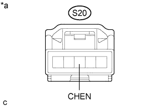
Text in Illustration *a Front view of wire harness connector
(to Electric Vehicle Charger Assembly)
Measure the voltage according to the value(s) in the table below.
Standard Voltage Tester Connection Condition Specified Condition S20-3 (CHEN) - Body ground Power switch on (IG) Below 1.5 V Note
Turning the power switch on (IG) with the electric vehicle charger assembly connector disconnected causes other DTCs to be stored. Clear the DTCs after performing this inspection.
-
Turn the power switch off.
-
Reconnect the S20 electric vehicle charger assembly connector.
NG 
CHECK HARNESS AND CONNECTOR (+B SHORT) Click here
OK
-
-
CHECK ELECTRIC VEHICLE CHARGER ASSEMBLY (CHEN VOLTAGE)
CAUTION:
Be sure to wear insulated gloves.
-
Check that the service plug grip is not installed.
Note
After removing the service plug grip, do not turn the power switch on (READY), unless instructed by the repair manual because this may cause a malfunction.
-
Disconnect the S20 electric vehicle charger assembly connector.
-
Turn the power switch on (IG).
-
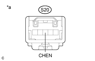
Text in Illustration *a Component without harness connected
(Electric Vehicle Charger Assembly)
Measure the voltage according to the value(s) in the table below.
Standard Voltage Tester Connection Condition Specified Condition S20-3 (CHEN) - Body ground Power switch on (IG) Below 1.5 V Note
Turning the power switch on (IG) with the electric vehicle charger assembly connector disconnected causes other DTCs to be stored. Clear the DTCs after performing this inspection.
-
Turn the power switch off.
-
Reconnect the S20 electric vehicle charger assembly connector.
NG
REPLACE ELECTRIC VEHICLE CHARGER ASSEMBLY Click here
OK
-
-
CHECK PLUGIN CHARGE CONTROL ECU ASSEMBLY (CHECK WAVEFORM)
-
Turn the power switch on (IG).
-
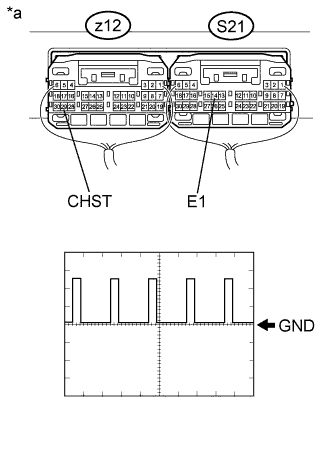
Text in Illustration *a Component with harness connected
(Plugin Charge Control ECU Assembly)
Connect an oscilloscope between the plugin charge control ECU assembly terminals specified in the table below, and measure the waveform.
Item Content Terminal z12-29 (CHST) - S21-14 (E1) Equipment Setting 5 V/DIV., 50 ms/DIV. Condition Power switch on (IG) -
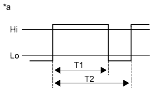
Text in Illustration *a Reference diagram for duty calculation Calculate duty (%) based on the CHST waveform.
Tech Tips
Calculate duty (%) using the following formula: Duty (%) = T1 / T2 x 100 (%)
Result Duty ratio of the waveform is 15 to 35% -
Turn the power switch off.
NG
REPLACE ELECTRIC VEHICLE CHARGER ASSEMBLY Click here
OK 
REPLACE PLUGIN CHARGE CONTROL ECU ASSEMBLY Click here
-
-
CHECK HARNESS AND CONNECTOR (+B SHORT)
CAUTION:
Be sure to wear insulated gloves.
-
Check that the service plug grip is not installed.
Note
After removing the service plug grip, do not turn the power switch on (READY), unless instructed by the repair manual because this may cause a malfunction.
-
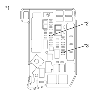
Text in Illustration *1 Engine Room Relay Block and Junction Block Assembly *2 AM2 Fuse *3 IGCT NO. 2 Fuse Remove the IGCT NO. 2 fuse and AM2 fuse from the engine room relay block and junction block assembly.
-
Disconnect the S20 electric vehicle charger assembly connector.
-
Text in Illustration *a Component with harness connected
(Power Management Control ECU)
Measure the resistance according to the value(s) in the table below.
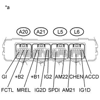
Standard Resistance Tester Connection Condition Specified Condition L6-23 (CHEN) - A20-2 (+B2) Power switch off 10 kΩ or higher L6-23 (CHEN) - A21-5 (+B1) Power switch off 10 kΩ or higher L6-23 (CHEN) - L5-1 (AM22) Power switch off 10 kΩ or higher L6-23 (CHEN) - L6-7 (AM21) Power switch off 10 kΩ or higher L6-23 (CHEN) - A21-6 (MREL) Power switch off 10 kΩ or higher L6-23 (CHEN) - A21-1 (IG2) Power switch off 10 kΩ or higher L6-23 (CHEN) - L6-1 (ACCD) Power switch off 10 kΩ or higher L6-23 (CHEN) - L6-2 (IG1D) Power switch off 10 kΩ or higher L6-23 (CHEN) - A21-2 (IG2D) Power switch off 10 kΩ or higher L6-23 (CHEN) - L5-14 (SPDI) Power switch off 10 kΩ or higher L6-23 (CHEN) - A20-16 (GI) Power switch off 10 kΩ or higher L6-23 (CHEN) - A20-4 (FCTL) Power switch off 10 kΩ or higher -
Reconnect the S20 electric vehicle charger assembly connector.
-
Install the IGCT NO. 2 fuse and AM2 fuse.
NG
CHECK HARNESS AND CONNECTOR (SHORT TO POWER SUPPLY WIRES) Click here
OK
-
-
CHECK HARNESS AND CONNECTOR (ELECTRIC VEHICLE CHARGER ASSEMBLY - POWER MANAGEMENT CONTROL ECU)
CAUTION:
Be sure to wear insulated gloves.
-
Check that the service plug grip is not installed.
Note
After removing the service plug grip, do not turn the power switch on (READY), unless instructed by the repair manual because this may cause a malfunction.
-
Disconnect the S20 electric vehicle charger assembly connector.
-
Disconnect the L6 power management control ECU connector.
-
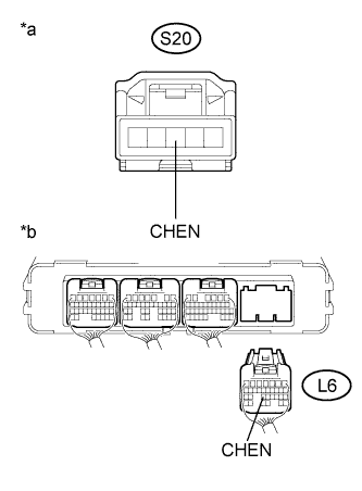
Text in Illustration *a Front view of wire harness connector
(to Electric Vehicle Charger Assembly)
*b Rear view of wire harness connector
(to Power Management Control ECU)
Measure the resistance according to the value(s) in the table below.
Standard Resistance (Check for Open) Tester Connection Condition Specified Condition S20-3 (CHEN) - L6-23 (CHEN) Power switch off Below 1 Ω Standard Resistance (Check for Short) Tester Connection Condition Specified Condition S20-3 (CHEN) or L6-23 (CHEN) - Body ground and other terminals Power switch off 10 kΩ or higher Tech Tips
As necessary, check that there is no short to power supply wires when performing the above wire harness inspection.
-
Reconnect the L6 power management control ECU connector.
-
Reconnect the S20 electric vehicle charger assembly connector.
NG
REPAIR OR REPLACE HARNESS OR CONNECTOR
OK
REPLACE POWER MANAGEMENT CONTROL ECU Click here
-
-
CHECK HARNESS AND CONNECTOR (SHORT TO POWER SUPPLY WIRES)
CAUTION:
Be sure to wear insulated gloves.
-
Check that the service plug grip is not installed.
Note
After removing the service plug grip, do not turn the power switch on (READY), unless instructed by the repair manual because this may cause a malfunction.
-
Text in Illustration *1 Engine Room Relay Block and Junction Block Assembly *2 AM2 Fuse *3 IGCT NO. 2 Fuse Remove the IGCT NO. 2 fuse and AM2 fuse from the engine room relay block and junction block assembly.
-
Disconnect the S20 electric vehicle charger assembly connector.
-
Disconnect the A20, A21, L5 and L6 power management control ECU connectors.
-
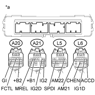
Text in Illustration *a Rear view of wire harness connector
(to Power Management Control ECU)
Measure the resistance according to the value(s) in the table below.
Standard Resistance Tester Connection Condition Specified Condition L6-23 (CHEN) - A20-2 (+B2) Power switch off 10 kΩ or higher L6-23 (CHEN) - A21-5 (+B1) Power switch off 10 kΩ or higher L6-23 (CHEN) - L5-1 (AM22) Power switch off 10 kΩ or higher L6-23 (CHEN) - L6-7 (AM21) Power switch off 10 kΩ or higher L6-23 (CHEN) - A21-6 (MREL) Power switch off 10 kΩ or higher L6-23 (CHEN) - A21-1 (IG2) Power switch off 10 kΩ or higher L6-23 (CHEN) - L6-1 (ACCD) Power switch off 10 kΩ or higher L6-23 (CHEN) - L6-2 (IG1D) Power switch off 10 kΩ or higher L6-23 (CHEN) - A21-2 (IG2D) Power switch off 10 kΩ or higher L6-23 (CHEN) - L5-14 (SPDI) Power switch off 10 kΩ or higher L6-23 (CHEN) - A20-16 (GI) Power switch off 10 kΩ or higher L6-23 (CHEN) - A20-4 (FCTL) Power switch off 10 kΩ or higher -
Reconnect the A20, A21, L5 and L6 power management control ECU connectors.
-
Reconnect the S20 electric vehicle charger assembly connector.
-
Install the IGCT NO. 2 fuse and AM2 fuse.
NG
REPAIR OR REPLACE HARNESS OR CONNECTOR
OK
REPLACE POWER MANAGEMENT CONTROL ECU Click here
-