HYBRID CONTROL SYSTEM, Diagnostic DTC:P3108-536
| DTC Code | DTC Name |
|---|---|
| P3108-536 | Lost Communication with A/C System Control Module |
DESCRIPTION
-
The power management control ECU detects a wiring malfunction in the serial communication line between it and the compressor with motor assembly.
| DTC No. | INF Code | DTC Detection Condition | Trouble Area |
|---|---|---|---|
| P3108 | 536 | A/C inverter malfunction |
|
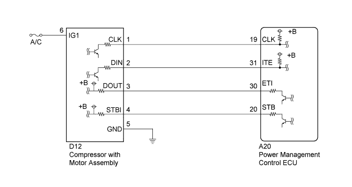
WIRING DIAGRAM
INSPECTION PROCEDURE
PROCEDURE
-
CHECK CONNECTOR CONNECTION CONDITION (POWER MANAGEMENT CONTROL ECU CONNECTOR)
-
Check the connector connections and contact pressure of the relevant terminals for the power management control ECU connectors Click here.
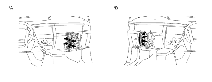
OK The connectors are connected securely and there are no contact pressure problems. Text in Illustration *A for LHD *B for RHD
NG 
CONNECT SECURELY
OK 
-
-
CHECK CONNECTOR CONNECTION CONDITION (COMPRESSOR WITH MOTOR ASSEMBLY CONNECTOR)
-
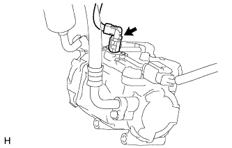
Check the connection of the low voltage connector of the compressor with motor assembly.
OK The connector is connected securely and there are no contact problems.
NG
CONNECT SECURELY
OK
-
-
CHECK HARNESS AND CONNECTOR (COMPRESSOR WITH MOTOR ASSEMBLY POWER SOURCE CIRCUIT)
-
Disconnect the D12 compressor with motor assembly connector.
-
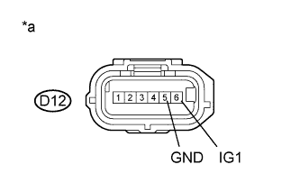
Text in Illustration *a Front view of wire harness connector
(to Compressor with Motor Assembly)
Measure the resistance according to the value(s) in the table below.
Standard Resistance Tester Connection Condition Specified Condition D12-5 (GND) - Body ground Power switch off Below 1 Ω -
Turn the power switch on (IG).
-
Measure the voltage according to the value(s) in the table below.
Standard Voltage Tester Connection Condition Specified Condition D12-6 (IG1) - D12-5 (GND) Power switch on (IG) 11 to 14 V Note
Turning the power switch on (IG) with the compressor with motor assembly connector disconnected causes other DTCs to be stored. Clear the DTCs after performing this inspection.
-
Turn the power switch off.
-
Reconnect the D12 compressor with motor assembly connector.
NG
REPAIR OR REPLACE HARNESS OR CONNECTOR
OK
-
-
CHECK DTC OUTPUT (HYBRID CONTROL)
-
Connect the GTS to the DLC3.
-
Turn the power switch on (READY).
-
Enter the following menus: Powertrain / Hybrid Control / Trouble Codes.
-
Check if DTCs are output.
Result Result Proceed to P3108-536 is output. A P3108-536 is not output. B -
Turn the power switch off.
B 
CHECK HARNESS AND CONNECTOR (POWER MANAGEMENT CONTROL ECU - COMPRESSOR WITH MOTOR ASSEMBLY) Click here
A
-
-
CHECK HARNESS AND CONNECTOR (POWER MANAGEMENT CONTROL ECU - COMPRESSOR WITH MOTOR ASSEMBLY)
-
Disconnect the A20 power management control ECU connector.
-
Disconnect the D12 compressor with motor assembly connector.
-
Turn the power switch on (IG).
-
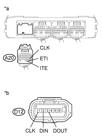
Text in Illustration *a Rear view of wire harness connector
(to Power Management Control ECU)
*b Front view of wire harness connector
(to Compressor with Motor Assembly)
Measure the voltage according to the value(s) in the table below.
Standard Voltage Tester Connection Condition Specified Condition A20-19 (CLK) - Body ground Power switch on (IG) Below 1 V A20-30 (ETI) - Body ground Power switch on (IG) Below 1 V A20-31 (ITE) - Body ground Power switch on (IG) Below 1 V Note
Turning the power switch on (IG) with the power management control ECU connector and the compressor with motor assembly connector disconnected causes other DTCs to be stored. Clear the DTCs after performing this inspection.
-
Turn the power switch off.
-
Measure the resistance according to the value(s) in the table below.
Standard Resistance (Check for Open) Tester Connection Condition Specified Condition A20-19 (CLK) - D12-1 (CLK) Power switch off Below 1 Ω A20-30 (ETI) - D12-3 (DOUT) Power switch off Below 1 Ω A20-31 (ITE) - D12-2 (DIN) Power switch off Below 1 Ω Standard Resistance (Check for Short) Tester Connection Condition Specified Condition A20-19 (CLK) or D12-1 (CLK) - Body ground and other terminals Power switch off 10 kΩ or higher A20-30 (ETI) or D12-3 (DOUT) - Body ground and other terminals Power switch off 10 kΩ or higher A20-31 (ITE) or D12-2 (DIN) - Body ground and other terminals Power switch off 10 kΩ or higher -
Reconnect the D12 compressor with motor assembly connector.
-
Reconnect the A20 power management control ECU connector.
NG
REPAIR OR REPLACE HARNESS OR CONNECTOR
OK
-
-
CHECK POWER MANAGEMENT CONTROL ECU
-
Disconnect the D12 compressor with motor assembly connector.
-
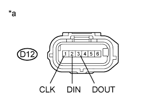
Text in Illustration *a Front view of wire harness connector
(to Compressor with Motor Assembly)
Measure the resistance according to the value(s) in the table below.
Standard Resistance Tester Connection Condition Specified Condition D12-3 (DOUT) - Body ground Power switch off 10 kΩ or higher -
Turn the power switch on (IG).
-
Measure the voltage according to the value(s) in the table below.
Standard Voltage Tester Connection Condition Specified Condition D12-1 (CLK) - Body ground Power switch on (IG) 11 to 14 V D12-2 (DIN) - Body ground Power switch on (IG) 11 to 14 V D12-3 (DOUT) - Body ground Power switch on (IG) Below 1 V Note
Turning the power switch on (IG) with the compressor with motor assembly connector disconnected causes other DTCs to be stored. Clear the DTCs after performing this inspection.
-
Turn the power switch off.
-
Reconnect the D12 compressor with motor assembly connector.
NG
REPLACE POWER MANAGEMENT CONTROL ECU Click here
OK
-
-
CHECK COMPRESSOR WITH MOTOR ASSEMBLY
-
Disconnect the A20 power management control ECU connector.
-
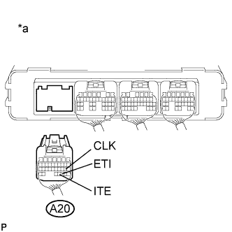
Text in Illustration *a Rear view of wire harness connector
(to Power Management Control ECU)
Measure the resistance according to the value(s) in the table below.
Standard Resistance Tester Connection Condition Specified Condition A20-19 (CLK) - Body ground Power switch off 10 kΩ or higher A20-31 (ITE) - Body ground Power switch off 10 kΩ or higher -
Turn the power switch on (IG).
-
Measure the voltage according to the value(s) in the table below.
Standard Voltage Tester Connection Condition Specified Condition A20-30 (ETI) - Body ground Power switch on (IG) 11 to 14 V A20-19 (CLK) - Body ground Power switch on (IG) Below 1 V A20-31 (ITE) - Body ground Power switch on (IG) Below 1 V Note
Turning the power switch on (IG) with the power management control ECU connector disconnected causes other DTCs to be stored. Clear the DTCs after performing this inspection.
-
Turn the power switch off.
-
Reconnect the A20 power management control ECU connector.
NG
REPLACE COMPRESSOR WITH MOTOR ASSEMBLY Click here
OK 
REPLACE POWER MANAGEMENT CONTROL ECU Click here
-
-
CHECK HARNESS AND CONNECTOR (POWER MANAGEMENT CONTROL ECU - COMPRESSOR WITH MOTOR ASSEMBLY)
-
Disconnect the A20 power management control ECU connector.
-
Disconnect the D12 compressor with motor assembly connector.
-
Turn the power switch on (IG).
-
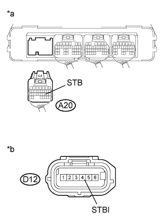
Text in Illustration *a Rear view of wire harness connector
(to Power Management Control ECU)
*b Front view of wire harness connector
(to Compressor with Motor Assembly)
Measure the voltage according to the value(s) in the table below.
Standard Voltage Tester Connection Condition Specified Condition A20-20 (STB) - Body ground Power switch on (IG) Below 1 V Note
Turning the power switch on (IG) with the power management control ECU connector disconnected causes other DTCs to be stored. Clear the DTCs after performing this inspection.
-
Turn the power switch off.
-
Measure the resistance according to the value(s) in the table below.
Standard Resistance (Check for Open) Tester Connection Condition Specified Condition A20-20 (STB) - D12-4 (STBI) Power switch off Below 1 Ω Standard Resistance (Check for Short) Tester Connection Condition Specified Condition A20-20 (STB) or D12-4 (STBI) - Body ground and other terminals Power switch off 10 kΩ or higher -
Reconnect the D12 compressor with motor assembly connector.
-
Reconnect the A20 power management control ECU connector.
NG
REPAIR OR REPLACE HARNESS OR CONNECTOR
OK
-
-
CHECK POWER MANAGEMENT CONTROL ECU
-
Disconnect the D12 compressor with motor assembly connector.
-
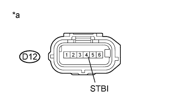
Text in Illustration *a Front view of wire harness connector
(to Compressor with Motor Assembly)
Measure the resistance according to the value(s) in the table below.
Standard Resistance Tester Connection Condition Specified Condition D12-4 (STBI) - Body ground Power switch off 10 kΩ or higher -
Turn the power switch on (IG).
-
Measure the voltage according to the value(s) in the table below.
Standard Voltage Tester Connection Condition Specified Condition D12-4 (STBI) - Body ground Power switch on (IG) Below 1 V Note
Turning the power switch on (IG) with the compressor with motor assembly connector disconnected causes other DTCs to be stored. Clear the DTCs after performing this inspection.
-
Turn the power switch off.
-
Reconnect the D12 compressor with motor assembly connector.
NG
REPLACE POWER MANAGEMENT CONTROL ECU Click here
OK
-
-
CHECK COMPRESSOR WITH MOTOR ASSEMBLY
-
Disconnect the A20 power management control ECU connector.
-
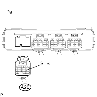
Text in Illustration *a Rear view of wire harness connector
(to Power Management Control ECU)
Measure the resistance according to the value(s) in the table below.
Standard Resistance Tester Connection Condition Specified Condition A20-20 (STB) - Body ground Power switch off 10 kΩ or higher -
Turn the power switch on (IG).
-
Measure the voltage according to the value(s) in the table below.
Standard Voltage Tester Connection Condition Specified Condition A20-20 (STB) - Body ground Power switch on (IG) 11 to 14 V Note
Turning the power switch on (IG) with the power management control ECU connector disconnected causes other DTCs to be stored. Clear the DTCs after performing this inspection.
-
Turn the power switch off.
-
Reconnect the A20 power management control ECU connector.
NG
REPLACE COMPRESSOR WITH MOTOR ASSEMBLY Click here
OK
REPLACE POWER MANAGEMENT CONTROL ECU Click here
-