HYBRID BATTERY SYSTEM, Diagnostic DTC:P0A9C-123, P0AC6-123, P0ACB-123, P3065-123
| DTC Code | DTC Name |
|---|---|
| P0A9C-123 | Hybrid Battery Temperature Sensor "A" Range / Performance |
| P0AC6-123 | Hybrid Battery Temperature Sensor "B" Range / Performance |
| P0ACB-123 | Hybrid Battery Temperature Sensor "C" Range / Performance |
| P3065-123 | Hybrid Battery Temperature Sensor Range/Performance Stuck "A" |
DESCRIPTION
-
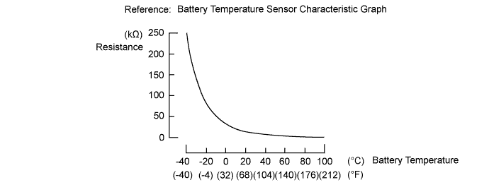
The battery temperature sensors are provided at 12 locations of the HV battery. The resistance of the thermistor, which is built into each battery temperature sensor, varies in accordance with changes in the HV battery temperature. The lower the battery temperature, the higher the thermistor resistance. Conversely, the higher the temperature, the lower the resistance. The battery smart unit uses the battery temperature sensors to detect the HV battery temperature, and sends the detected value to the power management control ECU. Based on the results of this detection, the power management control ECU controls the blower fan. (The blower fan starts when HV battery temperature rises above a predetermined level.)
Temperature Sensor Identification Cross Reference Table DTC Title Sensor Battery Temperature Sensor GTS Display A 0 1 B 1 2 C 2 3 Tech Tips
For example, sensor A in the DTC title is battery temperature sensor (No. 0). This sensor is displayed as Temp of Batt TB1 in the Data List.
| DTC No. | INF Code | DTC Detection Condition | Trouble Area |
|---|---|---|---|
| P0A9C | 123 | When the battery temperature sensor performance is abnormal (1 trip detection/2 trip detection) |
|
| P0AC6 | |||
| P0ACB | |||
| P3065 |
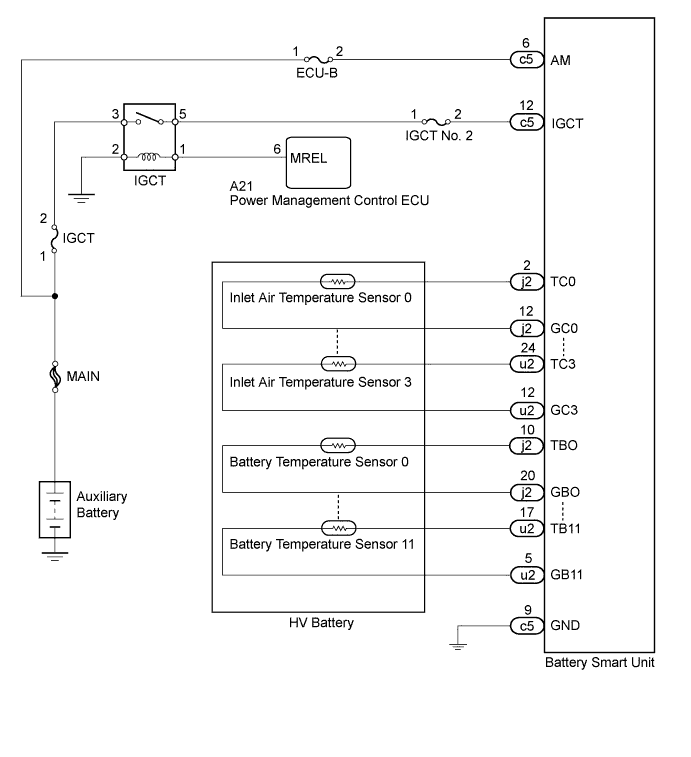
WIRING DIAGRAM
INSPECTION PROCEDURE
CAUTION:
-
Before inspecting the high-voltage system or disconnecting the low voltage connector of the inverter with converter assembly or electric vehicle charger assembly, turn the power switch off. Also, take safety precautions such as wearing insulated gloves and removing the service plug grip to prevent electrical shocks. After removing the service plug grip, put it in your pocket to prevent other technicians from accidentally reconnecting it while you are working on the high-voltage system.
-
After removing the service plug grip, wait for at least 10 minutes before touching any of the high-voltage connectors or terminals. After waiting for 10 minutes, check the voltage at the terminals in the inspection point in the inverter with converter assembly. The voltage should be 0 V before beginning work Click here.
Tech Tips
Waiting for at least 10 minutes is required to discharge the high-voltage capacitor inside the inverter with converter assembly and electric vehicle charger assembly.
-
When disposing of HV batteries and hybrid vehicle supply stack sub-assemblies, make sure to return them through an authorized collection agent who is capable of handling them safely. If they are returned via the manufacturer specified route, they will be returned properly and in a safe manner by an authorized collection agent.
-
Before returning the HV battery, make sure to perform recovery inspection Click here.
-
Before returning the hybrid vehicle supply stack sub-assembly, make sure to perform recovery inspection Click here.
-
Make a note of the output DTCs as some of them may be necessary for recovery inspection of the HV battery and hybrid vehicle supply stack sub-assemblies.
Note
After turning the power switch off, waiting time may be required before disconnecting the cable from the negative (-) auxiliary battery terminal. Therefore, make sure to read the disconnecting the cable from the negative (-) auxiliary battery terminal notices before proceeding with work Click here.
PROCEDURE
-
CHECK DTC OUTPUT (HYBRID CONTROL)
-
Connect the GTS to the DLC3.
-
Turn the power switch on (IG).
-
Enter the following menus: Powertrain / Hybrid Control / Trouble Codes.
-
Read output DTCs.
Result Result Proceed to P31AB-123, P1A61-123 ,P1A64-123, P1A67-123 is not output A P31AB-123, P1A61-123 ,P1A64-123, P1A67-12 is output B -
Disconnect the GTS from the DLC3.
-
Turn the power switch off.
B 
GO TO DTC CHART (HYBRID BATTERY SYSTEM) Click here
A 
-
-
CHECK DTC OUTPUT (HYBRID CONTROL)
-
Connect the GTS to the DLC3.
-
Turn the power switch on (IG).
-
Enter the following menus: Powertrain / Hybrid Control / Trouble Codes.
-
Read output DTCs Click here.
Result Result Proceed to P0AFC-123 is not output. A P0AFC-123 is also output. B -
Disconnect the GTS from the DLC3.
B
GO TO DTC CHART (P0AFC-123) Click here
A
-
-
CHECK HARNESS AND CONNECTOR (BATTERY TEMPERATURE SENSOR)
CAUTION:
Be sure to wear insulated gloves and protective goggles.
-
Check that the service plug grip is not installed.
Note
After removing the service plug grip, do not turn the power switch on (READY), unless instructed by the repair manual because this may cause a malfunction.
-
Remove the upper hybrid battery cover sub-assembly Click here.
-
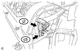
Disconnect the j2 and c5 battery smart unit connectors.
-
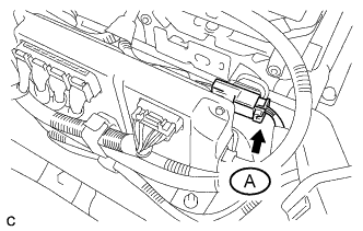
Disconnect the connector A.
-
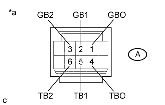
Text in Illustration *a Front view of No. 1 hybrid vehicle supply stack sub-assembly connector
(Intermediate wire harness connector)
Measure the resistance of the circuit for the malfunctioning sensor (battery temperature sensor 0 to 2).
Tester Connection Tester Connection Battery Temperature Sensor No. A-4 (TBO) - A-1 (GBO) 0 A-5 (TB1) - A-2 (GB1) 1 A-6 (TB2) - A-3 (GB2) 2 Standard Resistance Thermistor Temperature Condition Specified Condition 0 °C (32 °F) Power switch off 26.7 to 27.8 kΩ 25 °C (77 °F) Power switch off 9.9 to 10.1 kΩ 40 °C (104 °F) Power switch off 5.73 to 5.92 kΩ -
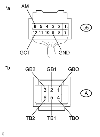
Text in Illustration *a Rear view of wire harness connector
(to Battery Smart Unit)
*b Front view of No. 1 hybrid vehicle supply stack sub-assembly connector
(Intermediate wire harness connector)
Measure the resistance according to the value(s) in the table below.
Standard Resistance Tester Connection Condition Specified Condition A-4 (TBO) - c5- 12 (IGCT) Power switch off 10 kΩ or more A-4 (TBO) - c5-6 (AM) Power switch off 10 kΩ or more A-4 (TBO) - c5- 9 (GND) Power switch off 10 kΩ or more A-1 (GBO) - c5- 12 (IGCT) Power switch off 10 kΩ or more A-1 (GBO) - c5- 6 (AM) Power switch off 10 kΩ or more A-1 (GBO) - c5- 9 (GND) Power switch off 10 kΩ or more A-5 (TB1) - c5- 12 (IGCT) Power switch off 10 kΩ or more A-5 (TB1) - c5-6 (AM) Power switch off 10 kΩ or more A-5(TB1) - c5- 9 (GND) Power switch off 10 kΩ or more A-2 (GB1) - c5- 12 (IGCT) Power switch off 10 kΩ or more A-2 (GB1) - c5- 6 (AM) Power switch off 10 kΩ or more A-2 (GB1) - c5- 9 (GND) Power switch off 10 kΩ or more A-6 (TB2) - c5- 12 (IGCT) Power switch off 10 kΩ or more A-6 (TB2) - c5-6 (AM) Power switch off 10 kΩ or more A-6 (TB2) - c5- 9 (GND) Power switch off 10 kΩ or more A-3 (GB2) - c5- 12 (IGCT) Power switch off 10 kΩ or more A-3 (GB2) - c5- 6 (AM) Power switch off 10 kΩ or more A-3 (GB2) - c5- 9 (GND) Power switch off 10 kΩ or more -
Reconnect the connector A.
-
Install the upper hybrid battery cover sub-assembly.
NG
REPLACE NO. 1 HYBRID VEHICLE SUPPLY STACK SUB-ASSEMBLY Click here
OK
-
-
CHECK HV BATTERY (BATTERY TEMPERATURE SENSOR)
CAUTION:
Be sure to wear insulated gloves.
-
Check that the service plug grip is not installed.
Note
After removing the service plug grip, do not turn the power switch on (READY), unless instructed by the repair manual because this may cause a malfunction.
-
Remove the No. 1 hybrid vehicle battery shield panel Click here.
-
Remove the No. 1 hybrid battery intake duct Click here.
-
Disconnect the j2 and c5 battery smart unit connectors.
-
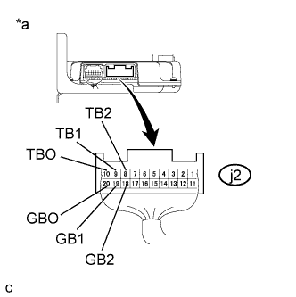
Text in Illustration *a Rear view of wire harness connector
(to Battery Smart Unit)
Measure the resistance of the circuit for the malfunctioning sensor (battery temperature sensor 0 to 2).
Tester Connection Tester Connection Battery Temperature Sensor No. j2-10 (TBO) - j2-20 (GBO) 0 j2-9 (TB1) - j2-19 (GB1) 1 j2-8 (TB2) - j2-18 (GB2) 2 Standard Resistance Thermistor Temperature Condition Specified Condition 0 °C (32 °F) Power switch off 26.7 to 27.8 kΩ 25 °C (77 °F) Power switch off 9.9 to 10.1 kΩ 40 °C (104 °F) Power switch off 5.73 to 5.92 kΩ -
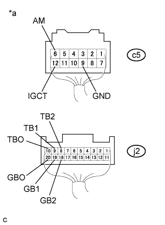
Text in Illustration *a Rear view of wire harness connector
(to Battery Smart Unit)
Measure the resistance according to the value(s) in the table below.
Standard Resistance Tester Connection Condition Specified Condition j2-10 (TB0) - c5- 12 (IGCT) Power switch off 10 kΩ or more j2-10 (TB0) - c5- 6 (AM) Power switch off 10 kΩ or more j2-10 (TB0) - c5- 9 (GND) Power switch off 10 kΩ or more j2-20 (GB0) - c5- 12 (IGCT) Power switch off 10 kΩ or more j2-20 (GB0) - c5- 6 (AM) Power switch off 10 kΩ or more j2-20 (GB0) - c5- 9 (GND) Power switch off 10 kΩ or more j2-9 (TB1) - c5- 12 (IGCT) Power switch off 10 kΩ or more j2-9 (TB1) - c5- 6 (AM) Power switch off 10 kΩ or more j2-9 (TB1) - c5- 9 (GND) Power switch off 10 kΩ or more j2-19 (GB1) - c5- 12 (IGCT) Power switch off 10 kΩ or more j2-19 (GB1) - c5- 6 (AM) Power switch off 10 kΩ or more j2-19 (GB1) - c5- 9 (GND) Power switch off 10 kΩ or more j2-8 (TB2) - c5- 12 (IGCT) Power switch off 10 kΩ or more j2-8 (TB2) - c5- 6 (AM) Power switch off 10 kΩ or more j2-8 (TB2) - c5- 9 (GND) Power switch off 10 kΩ or more j2-18 (GB2) - c5- 12 (IGCT) Power switch off 10 kΩ or more j2-18 (GB2) - c5- 6 (AM) Power switch off 10 kΩ or more j2-18 (GB2) - c5- 9 (GND) Power switch off 10 kΩ or more -
Reconnect the j2 and c5 battery smart unit connectors.
-
Install the No. 1 hybrid battery intake duct.
-
Install the No. 1 hybrid vehicle battery shield panel.
NG
REPLACE NO. 2 HYBRID VEHICLE SUPPLY STACK SUB-ASSEMBLY Click here
OK 
REPLACE BATTERY SMART UNIT Click here
-