HYBRID BATTERY SYSTEM, Diagnostic DTC:P0A97-123
| DTC Code | DTC Name |
|---|---|
| P0A97-123 | Hybrid Battery Pack Cooling Fan 2 Performance / Stuck OFF |
DESCRIPTION
-
Refer to the circuit description for DTC P0A84-123 Click here.
| DTC No. | INF Code | DTC Detection Condition | Trouble Area |
|---|---|---|---|
| P0A97 | 123 | The speed of the battery cooling blower assembly (No. 1) is not within the specified range (1 trip detection/2 trip detection) |
|
Tech Tips
The above DTC can be stored while the battery cooling blower assembly operates. When performing a reproduction test, drive the vehicle until "Temp of batt TB7to12" is stored in the Freeze Frame Data and then start the battery cooling blower assembly. This DTC is not detected when performing an Active Test of "Driving the Battery Cooling Fan".
WIRING DIAGRAM
Refer to the wiring diagram for DTC P0A84-123 Click here.
INSPECTION PROCEDURE
CAUTION:
-
Before inspecting the high-voltage system or disconnecting the low voltage connector of the inverter with converter assembly or electric vehicle charger assembly, turn the power switch off. Also, take safety precautions such as wearing insulated gloves and removing the service plug grip to prevent electrical shocks. After removing the service plug grip, put it in your pocket to prevent other technicians from accidentally reconnecting it while you are working on the high-voltage system.
-
After removing the service plug grip, wait for at least 10 minutes before touching any of the high-voltage connectors or terminals. After waiting for 10 minutes, check the voltage at the terminals in the inspection point in the inverter with converter assembly. The voltage should be 0 V before beginning work Click here.
Tech Tips
Waiting for at least 10 minutes is required to discharge the high-voltage capacitor inside the inverter with converter assembly and electric vehicle charger assembly.
Note
After turning the power switch off, waiting time may be required before disconnecting the cable from the negative (-) auxiliary battery terminal. Therefore, make sure to read the disconnecting the cable from the negative (-) auxiliary battery terminal notices before proceeding with work Click here.
PROCEDURE
-
CHECK DTC OUTPUT (HYBRID CONTROL)
-
Connect the GTS to the DLC3.
-
Turn the power switch on (IG).
-
Enter the following menus: Powertrain / Hybrid Control / Trouble Codes.
-
Read output DTCs Click here.
Result Result Proceed to P0AFC-123 is not output. A P0AFC-123 is also output. B -
Disconnect the GTS from the DLC3.
B 
GO TO DTC CHART (P0AFC-123) Click here
A 
-
-
CHECK DUCT AND BLOWER
-
Remove the rear deck trim cover Click here.
-
Remove the rear seat cushion assembly Click here.
-
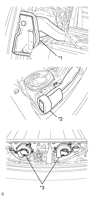
Text in Illustration *1 No. 2 Hybrid Battery Intake Duct *2 No. 1 Hybrid Battery Intake Duct *3 Battery Cooling Blower Assembly Check that the No. 1 hybrid battery intake duct, No. 2 hybrid intake duct and battery cooling blower are not disconnected, damaged, or clogged with foreign objects, and that the acoustical materials have not peeled.
OK The duct and blower are not disconnected, damaged, or clogged with foreign objects and the acoustical materials have not peeled. -
Install the rear seat cushion assembly.
-
Install the rear deck trim cover.
NG
CORRECT THE PROBLEM
OK
-
-
CLEAR DTC (HYBRID CONTROL)
-
Connect the GTS to the DLC3.
-
Turn the power switch on (IG).
-
Enter the following menus: Powertrain / Hybrid Control / Trouble Codes.
-
Clear the DTCs and freeze frame data Click here.
-
Perform a road test to charge and discharge the HV battery.
Tech Tips
2 trip detection logic is used. After the first road test, turn the power switch off and perform a road test again.
-
Disconnect the GTS from the DLC3.
-
Turn the power switch off.
NEXT
-
-
CHECK BATTERY COOLING BLOWER ASSEMBLY (NO. 1)
-
Remove the rear deck trim cover Click here.
-
Connect the GTS to the DLC3.
-
Turn the power switch on (IG).
-
Enter the following menu items: Powertrain / Hybrid Control / Active Test / Driving the Battery Cooling Fan.
Note
If the active test cannot be performed, skip it and proceed to the next step to check the Data List values (VMF Fan Motor Voltage 1, VMF Fan Motor Voltage 2). In accordance with fail-safe system operation, the power management control ECU sends a command to operate the battery cooling fan.
-
Select each air volume mode (1 to 6) in the Battery Cooling Fan active test to operate the battery cooling blower assembly.
-
Enter the following menus: All Data / VMF Fan Motor Voltage 1, VMF Fan Motor Voltage 2.
-
Check that the Data List value (VMF Fan Motor Voltage 1) is abnormal while operating the cooling fans (battery cooling blower assemblies). (*1)
-
Turn the power switch off.
-
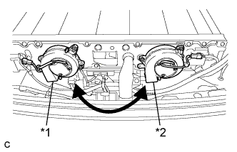
Text in Illustration *1 Battery Cooling Blower Assembly (No. 0) *2 Battery Cooling Blower Assembly (No. 1) Switch the battery cooling blower assembly (No. 0) with one of the battery cooling blower assembly (No. 1).
-
Turn the power switch on (IG).
-
Enter the following menu items: Powertrain / Hybrid Control / Active Test / Driving the Battery Cooling Fan.
Note
If the active test cannot be performed, skip it and proceed to the next step to check the Data List values (VMF Fan Motor Voltage 1, VMF Fan Motor Voltage 2). In accordance with fail-safe system operation, the power management control ECU sends a command to operate the battery cooling fan.
-
Select each air volume mode (1 to 6) in the Battery Cooling Fan active test to operate the battery cooling blower assembly.
-
Enter the following menus: All Data / VMF Fan Motor Voltage 1, VMF Fan Motor Voltage 2.
-
Check if the blower assembly (from *1 above) malfunctions in a different location while operating the cooling fans (battery cooling blower assemblies) using the Active Test.
Result Result Proceed to Malfunction is not reproduced in same blower when it is moved to another location A Malfunction is reproduced in same blower when it is moved to another location B -
Disconnect the GTS from the DLC3.
-
Turn the power switch off.
-
Return the battery cooling blower assemblies to their original positions.
B
REPLACE BATTERY COOLING BLOWER ASSEMBLY (NO. 1) Click here
A
-
-
CHECK HARNESS AND CONNECTOR (BATTERY COOLING BLOWER ASSEMBLY (NO. 1) - POWER MANAGEMENT CONTROL ECU)
-
Check that the service plug grip is not installed.
Note
After removing the service plug grip, do not turn the power switch on (READY), unless instructed by the repair manual because this may cause a malfunction.
-
Remove the rear deck trim cover Click here.
-
Disconnect the S18 battery cooling blower assembly (No. 1) connector.
-
Disconnect the A20 power management control ECU connector Click here.
-
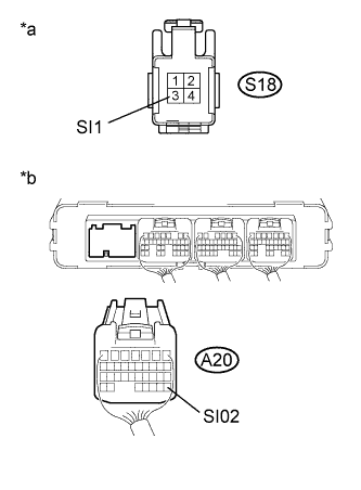
Text in Illustration *a Front view of wire harness connector
(to Battery Cooling Blower Assembly (No. 1))
*b Rear view of wire harness connector
(to Power Management Control ECU)
Measure the resistance according to the value(s) in the table below.
Standard Resistance Tester Connection Specified Condition S18-3 (SI1) or A20-28 (SI02) - Body ground 10 kΩ or higher S18-3 (SI1) - A20-28 (SI02) Below 1 Ω -
Reconnect the S18 battery cooling blower assembly (No. 1) connector.
-
Install the rear deck trim cover.
-
Reconnect the A20 power management control ECU connector.
NG
REPAIR OR REPLACE HARNESS OR CONNECTOR
OK
-
-
CHECK POWER MANAGEMENT CONTROL ECU (GROUND SHORT CHECK)
-
Remove the power management control ECU Click here.
-
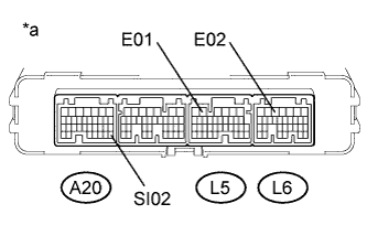
Text in Illustration *a Component without harness connected
(Power Management Control ECU)
Measure the resistance according to the value(s) in the table below.
Standard Resistance Tester Connection Condition Specified Condition A20-28 (SI02) - L5-5 (E01) Power switch off 10 kΩ or higher A20-28 (SI02) - L6-5 (E02) Power switch off 10 kΩ or higher -
Install the power management control ECU.
NG
REPLACE POWER MANAGEMENT CONTROL ECU Click here
OK
-
-
CHECK HV BATTERY ((BATTERY TEMPERATURE SENSOR)
CAUTION:
Be sure to wear insulated gloves.
-
Check that the service plug grip is not installed.
Note
After removing the service plug grip, do not turn the power switch on (READY), unless instructed by the repair manual because this may cause a malfunction.
-
Remove the No. 1 hybrid vehicle battery shield panel Click here.
-
Remove the No. 1 hybrid battery intake duct Click here.
-
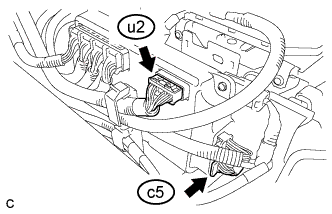
Disconnect the u2 and c5 battery smart unit connectors.
-
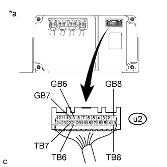
Text in Illustration *a Rear view of wire harness connector
(to Battery Smart Unit)
Measure the resistance of the circuit for the malfunctioning sensor (battery temperature sensor 0 to 2).
Tester Connection Tester Connection Battery Temperature Sensor No. u2-21 (TB6) - u2-9 (GB6) 6 u2-22 (TB7) - u2-10 (GB7) 7 u2-13 (TB8) - u2-1 (GB8) 8 Standard Resistance Thermistor Temperature Condition Specified Condition 0 °C (32 °F) Power switch off 26.7 to 27.8 kΩ 25 °C (77 °F) Power switch off 9.9 to 10.1 kΩ 40 °C (104 °F) Power switch off 5.73 to 5.92 kΩ -
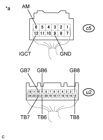
Text in Illustration *a Rear view of wire harness connector
(to Battery Smart Unit)
Measure the resistance according to the value(s) in the table below.
Standard Resistance Tester Connection Condition Specified Condition u2-21 (TB6) - c5- 12 (IGCT) Power switch off 10 kΩ or more u2-21 (TB6) - c5- 6 (AM) Power switch off 10 kΩ or more u2-21 (TB6) - c5- 9 (GND) Power switch off 10 kΩ or more u2-9 (GB6) - c5- 12 (IGCT) Power switch off 10 kΩ or more u2-9 (GB6) - c5- 6 (AM) Power switch off 10 kΩ or more u2-9 (GB6) - c5- 9 (GND) Power switch off 10 kΩ or more u2-22 (TB7) - c5- 12 (IGCT) Power switch off 10 kΩ or more u2-22 (TB7) - c5- 6 (AM) Power switch off 10 kΩ or more u2-22 (TB7) - c5- 9 (GND) Power switch off 10 kΩ or more u2-10 (GB7) - c5- 12 (IGCT) Power switch off 10 kΩ or more u2-10 (GB7) - c5- 6 (AM Power switch off 10 kΩ or more u2-10 (GB7) - c5- 9 (GND) Power switch off 10 kΩ or more u2-13 (TB8) - c5- 12 (IGCT) Power switch off 10 kΩ or more u2-13 (TB8) - c5- 6 (AM) Power switch off 10 kΩ or more u2-13 (TB8) - c5- 9 (GND) Power switch off 10 kΩ or more u2-1 (GB8) - c5- 12 (IGCT) Power switch off 10 kΩ or more u2-1 (GB8) - c5- 6 (AM) Power switch off 10 kΩ or more u2-1 (GB8) - c5- 9 (GND) Power switch off 10 kΩ or more -
Reconnect the u2 and c5 battery smart unit connectors.
-
Install the No. 1 hybrid battery intake duct.
-
Install the No. 1 hybrid vehicle battery shield panel.
NG
REPLACE NO. 3 HYBRID VEHICLE SUPPLY STACK SUB-ASSEMBLY Click here
OK
-
-
CHECK HARNESS AND CONNECTOR ((BATTERY TEMPERATURE SENSOR)
CAUTION:
Be sure to wear insulated gloves and protective goggles.
-
Check that the service plug grip is not installed.
Note
After removing the service plug grip, do not turn the power switch on (READY), unless instructed by the repair manual because this may cause a malfunction.
-
Remove the upper hybrid battery cover sub-assembly Click here.
-
Disconnect the u2 and c5 battery smart unit connectors.
-
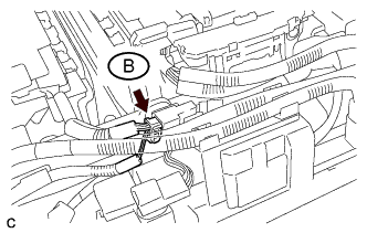
Disconnect the connector B.
-
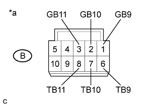
Text in Illustration *a Front view of No. 4 hybrid vehicle supply stack sub-assembly connector
(Intermediate wire harness connector)
Measure the resistance of the circuit for the malfunctioning sensor (battery temperature sensor 0 to 2).
Tester Connection Tester Connection Battery Temperature Sensor No. B-6 (TB9) - B-1 (GB9) 9 B-7 (TB10) - B-2 (GB10) 10 B-8 (TB11) - B-3 (GB11) 11 Standard Resistance Thermistor Temperature Condition Specified Condition 0 °C (32 °F) Power switch off 26.7 to 27.8 kΩ 25 °C (77 °F) Power switch off 9.9 to 10.1 kΩ 40 °C (104 °F) Power switch off 5.73 to 5.92 kΩ -
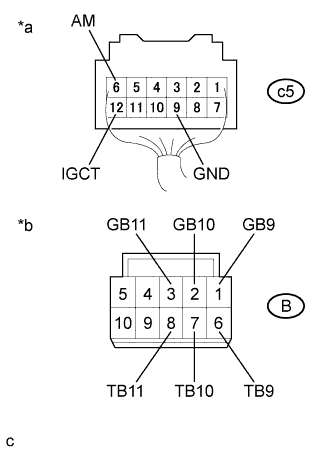
Text in Illustration *a Rear view of wire harness connector
(to Battery Smart Unit)
*b Front view of No. 4 hybrid vehicle supply stack sub-assembly connector
(Intermediate wire harness connector)
Measure the resistance according to the value(s) in the table below.
Standard Resistance Tester Connection Condition Specified Condition B-6 (TB9) - c5- 12 (IGCT) Power switch off 10 kΩ or more B-6 (TB9) - c5-6 (AM) Power switch off 10 kΩ or more B-6 (TB9) - c5- 9 (GND) Power switch off 10 kΩ or more B-1 (GB9) - c5- 12 (IGCT) Power switch off 10 kΩ or more B-1 (GB9) - c5- 6 (AM) Power switch off 10 kΩ or more B-1 (GB9) - c5- 9 (GND) Power switch off 10 kΩ or more B-7 (TB10) - c5- 12 (IGCT) Power switch off 10 kΩ or more B-7 (TB10) - c5- 6 (AM) Power switch off 10 kΩ or more B-7 (TB10) - c5- 9 (GND) Power switch off 10 kΩ or more B-2 (GB10) - c5- 12 (IGCT) Power switch off 10 kΩ or more B-2 (GB10) - c5- 6 (AM) Power switch off 10 kΩ or more B-2 (GB10) - c5- 9 (GND) Power switch off 10 kΩ or more B-8 (TB11) - c5- 12 (IGCT) Power switch off 10 kΩ or more B-8 (TB11) - c5- 6 (AM) Power switch off 10 kΩ or more B-8 (TB11) - c5- 9 (GND) Power switch off 10 kΩ or more B-3 (GB11) - c5- 12 (IGCT) Power switch off 10 kΩ or more B-3 (GB11) - c5- 6 (AM) Power switch off 10 kΩ or more B-3 (GB11) - c5- 9 (GND) Power switch off 10 kΩ or more -
Reconnect the connector B.
-
Install the No. 1 hybrid vehicle battery carrier bracket sub-assembly.
NG
REPLACE NO. 4 HYBRID VEHICLE SUPPLY STACK SUB-ASSEMBLY Click here
OK
-
-
CHECK HV BATTERY ((BATTERY TEMPERATURE SENSOR)
CAUTION:
Be sure to wear insulated gloves.
-
Check that the service plug grip is not installed.
Note
After removing the service plug grip, do not turn the power switch on (READY), unless instructed by the repair manual because this may cause a malfunction.
-
Remove the No. 1 hybrid vehicle battery shield panel Click here.
-
Remove the No. 1 hybrid battery intake duct Click here.
-
Disconnect the u2 and c5 battery smart unit connectors.
-
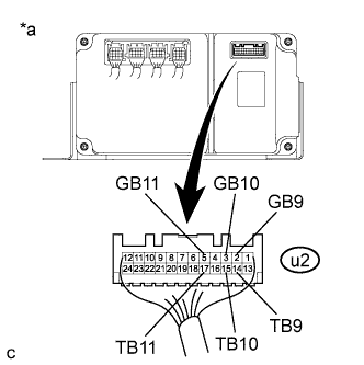
Text in Illustration *a Rear view of wire harness connector
(to Battery Smart Unit)
Measure the resistance of the circuit for the malfunctioning sensor (battery temperature sensor 0 to 2).
Tester Connection Tester Connection Battery Temperature Sensor No. u2-14 (TB9) - u2-2 (GB9) 9 u2-15 (TB10) - u2-3 (GB10) 10 u2-17 (TB11) - u2-5 (GB11) 11 Standard Resistance Thermistor Temperature Condition Specified Condition 0 °C (32 °F) Power switch off 26.7 to 27.8 kΩ 25 °C (77 °F) Power switch off 9.9 to 10.1 kΩ 40 °C (104 °F) Power switch off 5.73 to 5.92 kΩ -
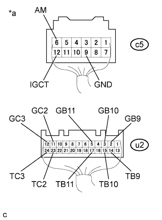
Text in Illustration *a Rear view of wire harness connector
(to Battery Smart Unit)
Measure the resistance according to the value(s) in the table below.
Standard Resistance Tester Connection Condition Specified Condition u2-14 (TB9) - c5- 12 (IGCT) Power switch off 10 kΩ or higher u2-14 (TB9) - c5- 6 (AM) Power switch off 10 kΩ or higher u2-14 (TB9) - c5- 9 (GND) Power switch off 10 kΩ or higher u2-2 (GB9) - c5- 12 (IGCT) Power switch off 10 kΩ or higher u2-2 (GB9) - c5- 6 (AM) Power switch off 10 kΩ or higher u2-2 (GB9) - c5- 9 (GND) Power switch off 10 kΩ or higher u2-15 (TB10) - c5- 12 (IGCT) Power switch off 10 kΩ or higher u2-15 (TB10) - c5- 6 (AM) Power switch off 10 kΩ or higher u2-15 (TB10) - c5- 9 (GND) Power switch off 10 kΩ or higher u2-3 (GB10) - c5- 12 (IGCT) Power switch off 10 kΩ or higher u2-3 (GB10) - c5- 6 (AM) Power switch off 10 kΩ or higher u2-3 (GB10) - c5- 9 (GND) Power switch off 10 kΩ or higher u2-17 (TB11) - c5- 12 (IGCT) Power switch off 10 kΩ or higher u2-17 (TB11) - c5- 6 (AM) Power switch off 10 kΩ or higher u2-17 (TB11) - c5- 9 (GND) Power switch off 10 kΩ or higher u2-5 (GB11) - c5- 12 (IGCT) Power switch off 10 kΩ or higher u2-5 (GB11) - c5- 6 (AM) Power switch off 10 kΩ or higher u2-5 (GB11) - c5- 9 (GND) Power switch off 10 kΩ or higher u2-23 (TC2) - c5- 12 (IGCT) Power switch off 10 kΩ or higher u2-23 (TC2) - c5- 6 (AM) Power switch off 10 kΩ or higher u2-23 (TC2) - c5- 9 (GND) Power switch off 10 kΩ or higher u2-11 (GC2) - c5- 12 (IGCT) Power switch off 10 kΩ or higher u2-11 (GC2) - c5- 6 (AM) Power switch off 10 kΩ or higher u2-11 (GC2) - c5- 9 (GND) Power switch off 10 kΩ or higher u2-24 (TC3) - c5- 12 (IGCT) Power switch off 10 kΩ or higher u2-24 (TC3) - c5- 6 (AM) Power switch off 10 kΩ or higher u2-24 (TC3) - c5- 9 (GND) Power switch off 10 kΩ or higher u2-12 (GC3) - c5- 12 (IGCT) Power switch off 10 kΩ or higher u2-12 (GC3) - c5- 6 (AM) Power switch off 10 kΩ or higher u2-12 (GC3) - c5- 9 (GND) Power switch off 10 kΩ or higher -
Reconnect the u2 and c5 battery smart unit connectors.
-
Install the No. 1 hybrid battery intake duct.
-
Install the No. 1 hybrid vehicle battery shield panel.
NG
REPLACE NO. 3 HYBRID VEHICLE SUPPLY STACK SUB-ASSEMBLY Click here
OK 
REPLACE BATTERY SMART UNIT Click here
-