HYBRID CONTROL SYSTEM, Diagnostic DTC:P0AA6-526, P0AA6-611, P0AA6-612, P0AA6-613, P0AA6-614
| DTC Code | DTC Name |
|---|---|
| P0AA6-526 | Hybrid Battery Voltage System Isolation Fault |
| P0AA6-611 | Hybrid Battery Voltage System Isolation Fault |
| P0AA6-612 | Hybrid Battery Voltage System Isolation Fault |
| P0AA6-613 | Hybrid Battery Voltage System Isolation Fault |
| P0AA6-614 | Hybrid Battery Voltage System Isolation Fault |
DESCRIPTION
The power management control ECU monitors the battery smart unit and detects insulation malfunctions in the high-voltage system.
| DTC No. | INF Code | DTC Detection Condition | Trouble Area |
|---|---|---|---|
| P0AA6 | 526(*1) | Insulation resistance between the high-voltage circuit and the body has decreased.*2 |
|
| P0AA6 | 611 | Insulation resistance of the high voltage circuit in the air conditioning system has decreased.*3 | Air conditioning system |
| P0AA6 | 612 | Insulation resistance of the HV battery area has decreased.*3 |
|
| P0AA6 | 613 | Insulation resistance of the transaxle area has decreased.*3 |
|
| P0AA6 | 614 | Insulation resistance of the high-voltage DC area has decreased.*3 |
|
Tech Tips
-
*1: INF code 526 is stored together with P0AA6.
-
*2: The insulation malfunction detection circuit in the battery voltage sensor monitors the insulation resistance between the high voltage circuits and body. If the insulation resistance decreases, the power management control ECU stores DTC P0AA6-526 and illuminates the MIL first.
-
*3: If the following operations are performed within the same trip after DTC P0AA6-526 is stored, just one of the related DTCs (P0AA6-611, 612, 613 or 614) will be stored.
-
Apply the parking brake firmly.
-
Wait for 1 minute or more with the vehicle stopped, the brake pedal firmly depressed, the power switch on (READY), drive (D) selected and the air conditioning system on (Lo/COOL MAX, blower speed HI), then turn the power switch off and wait for 1 minute or more.
-
If DTC P0AA6 is stored, the vehicle cannot start.
-
When measuring insulation resistance using a megohmmeter, measure the resistance while jiggling the high voltage wire harness.
WIRING DIAGRAM
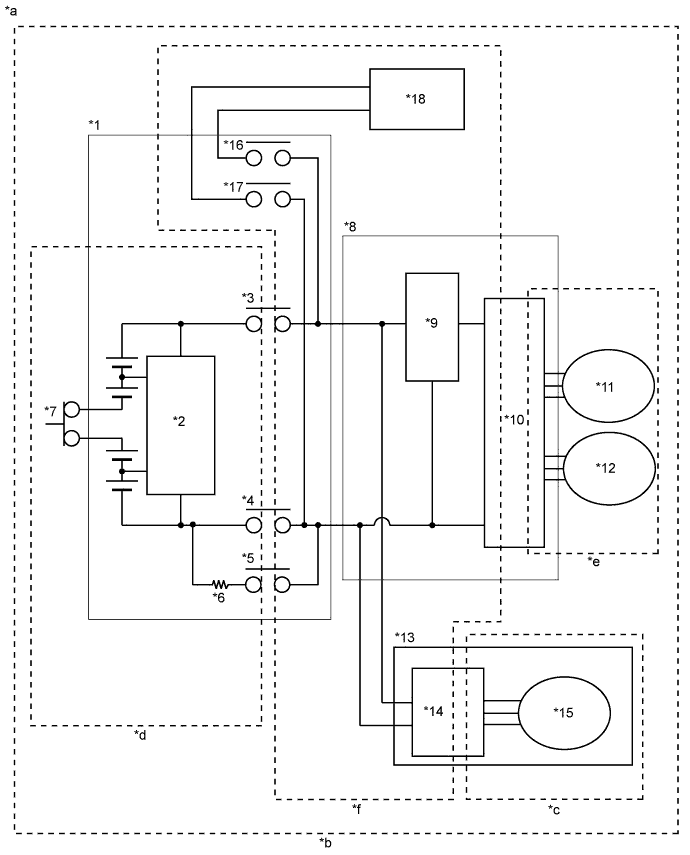
| *1 | HV Battery | *2 | Battery Smart Unit |
| *3 | SMRB | *4 | SMRG |
| *5 | SMRP | *6 | System Main Resistor |
| *7 | Service Plug Grip | *8 | Inverter with Converter Assembly |
| *9 | Boost Converter | *10 | Inverter |
| *11 | MG1 | *12 | MG2 |
| *13 | Compressor with Motor Assembly | *14 | A/C Inverter |
| *15 | A/C Motor | *16 | CHRB |
| *17 | CHRG | *18 | Electric vehicle charger assembly |
| *a | High-voltage Areas | *b | INF Code 526 Vehicle Insulation Resistance Reduction Area |
| *c | INF Code 611 Air Conditioning System Area | *d | INF Code 612 HV Battery Area |
| *e | INF Code 613 Transaxle Area | *f | INF Code 614 High Voltage Direct Current Area |
SYSTEM DESCRIPTION
Tech Tips
If a decrease in insulation resistance cannot be confirmed using a megohmmeter, check the Short Wave Highest Val in the Data List.
-
Characteristics of Short Wave Highest Value
-
The Data List item Short Wave Highest Val and insulation resistance have the relationship shown in the table below. Short Wave Highest Val decreases with a decrease in insulation resistance. However, in some cases, even though the insulation resistance of the vehicle is normal, Short Wave Highest Val may decrease. Therefore, check Short Wave Highest Val under the following conditions:
-
Approximately 1 minute has passed since the power switch was turned on (IG).*1
-
There is no difference between the system voltages (Power Resource VB, VL-Voltage before Boosting, and VH-Voltage after Boosting).*2
Short Wave Highest Value Trouble Area Both conditions (*1 and *2) are met and Short Wave Highest Val is approximately 0 V Since the insulation resistance is close to 0 Ω, there is a strong possibility of interference with a metal object. Both conditions (*1 and *2) are met and Short Wave Highest Val is between 0 and 5 V Since the insulation resistance is several hundred kilo ohms, there is a strong possibility of the presence of fluid such as coolant.
-
-
-
How to Determine Part with Insulation Malfunction
-
Jiggle the high-voltage wire harness to check if the resistance to body ground changes with the position of the wire harness or force applied.
-
Repeat rotating and stopping of the MG1, MG2 and compressor with motor assembly. Check that the Short Wave Highest Val does not decrease (for example if the motor stops with foreign matter forming a leak path) when the motor stops, or that the Short Wave Highest Val does not return to normal (for example if foreign matter moves away from the leak path) when the motor rotates.
-
Increase the temperature of MG1and MG2. Check if the Short Wave Highest Val decreases with the temperature increase.
-
Check that the transaxle fluid is not cloudy and the coolant level in the reserve tank has not dropped as the transaxle fluid will become cloudy when mixed with coolant, resulting in low insulation resistance.
-
INSPECTION PROCEDURE
CAUTION:
-
When performing P0AA6 troubleshooting, use either a tool wrapped with vinyl insulation tape or a insulated tool. (It is extremely dangerous when a high-voltage charge passes through a non-insulated tool causing a short.)
-
Before inspecting the high-voltage system or disconnecting the low voltage connector of the inverter with converter assembly or electric vehicle charger assembly, turn the power switch off. Also, take safety precautions such as wearing insulated gloves and removing the service plug grip to prevent electrical shocks. After removing the service plug grip, put it in your pocket to prevent other technicians from accidentally reconnecting it while you are working on the high-voltage system.
-
After removing the service plug grip, wait for at least 10 minutes before touching any of the high-voltage connectors or terminals. After waiting for 10 minutes, check the voltage at the terminals in the inspection point in the inverter with converter assembly. The voltage should be 0 V before beginning work Click here.
Tech Tips
Waiting for at least 10 minutes is required to discharge the high-voltage capacitor inside the inverter with converter assembly and electric vehicle charger assembly.
-
When disposing of HV batteries and hybrid vehicle supply stack sub-assemblies, make sure to return them through an authorized collection agent who is capable of handling them safely. If they are returned via the manufacturer specified route, they will be returned properly and in a safe manner by an authorized collection agent.
-
Before returning the HV battery, make sure to perform recovery inspection Click here.
-
Before returning the hybrid vehicle supply stack sub-assembly, make sure to perform recovery inspection Click here.
-
Make a note of the output DTCs as some of them may be necessary for recovery inspection of the HV battery and hybrid vehicle supply stack sub-assemblies.
Note
After turning the power switch off, waiting time may be required before disconnecting the cable from the negative (-) auxiliary battery terminal. Therefore, make sure to read the disconnecting the cable from the negative (-) auxiliary battery terminal notices before proceeding with work Click here.
Tech Tips
When measuring insulation resistance using a megohmmeter, set the megohmmeter to 500 V.
PROCEDURE
-
CHECK DTC OUTPUT (HYBRID CONTROL)
-
Connect the GTS to the DLC3.
-
Turn the power switch on (IG).
-
Enter the following menus: Powertrain / Hybrid Control / Trouble Codes.
-
Check if DTCs are output.
Result Result Proceed to P0AA6 only is output. A P0AA6 and P0A1D (power management control ECU malfunction) are output. B P0AA6 and P0AA7 (malfunction in the battery smart unit) are output. C P0AA6 and P0AFC (Hybrid Battery Pack Sensor Module) are output. D -
Turn the power switch off.
B 
GO TO DTC CHART (P0A1D) Click here
C
GO TO DTC CHART (P0AA7) Click here
D
GO TO DTC CHART (P0AFC) Click here
A 
-
-
CHECK INFORMATION CODE
-
Turn the power switch on (IG).
-
Enter the following menus: Powertrain / Hybrid Control / Trouble Codes.
-
Access the freeze frame data of DTC P0AA6 and read the INF code.
Note
-
Information codes 611, 612, 613 and 614 are not stored with 526 simultaneously. If a drop in insulation resistance is detected and DTC P0AA6- 526 is output, wait for 1 minute with power switch on (READY), drive (D) selected and the air conditioning system on within the same trip, then turn the power switch off and wait for 1 minute to determine the information code (611, 612, 613 or 614).
-
If only DTC P0AA6-526 is output, perform the diagnosis procedure for INF code 526 to inspect all the high voltage circuits.
Result Result Proceed to 526 (decrease in the insulation resistance of the high-voltage circuit) only is output A 526 and 611 (decrease in the insulation resistance of the air conditioning system area) are output Refer to the troubleshooting procedures for P0AA6-611 (Air conditioning system) Click here
526 and 612 (decrease in the insulation resistance of the battery area) are output B 526 and 613 (decrease in the insulation resistance of the transaxle area) are output C 526 and 614 (decrease in the insulation resistance of the high-voltage DC area) are output D -
-
Turn the power switch off.
B 
CHECK HV BATTERY AREA Click here
C
CHECK INVERTER WITH CONVERTER ASSEMBLY Click here
D
CHECK HIGH VOLTAGE DIRECT CURRENT AREA Click here
A
-
-
CHECK HYBRID VEHICLE TRANSAXLE ASSEMBLY (MOTOR CABLE)
CAUTION:
Be sure to wear insulated gloves.
-
Check that the service plug grip is not installed.
Note
After removing the service plug grip, do not turn the power switch on (READY), unless instructed by the repair manual because this may cause a malfunction.
-
Remove the inverter cover from the inverter with converter assembly.
Tech Tips
Make sure that no foreign matter has entered or contaminated the inverter with converter assembly.
-
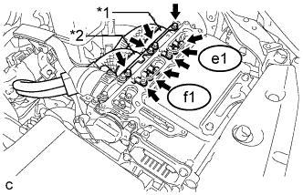
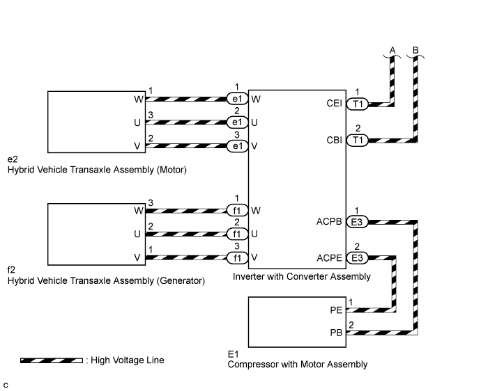
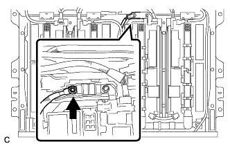
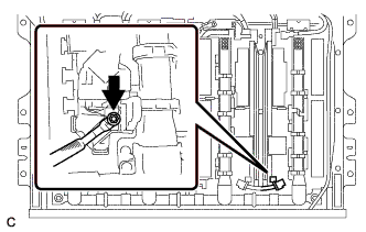
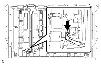
Text in Illustration *1 Motor Cable *2 Generator Cable Disconnect connector e1 and f1 of the motor cable and generator cable from the inverter with converter assembly.
-
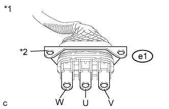
Text in Illustration *1 Motor Cable
(Inverter with Converter Assembly Side)
*2 Shield Ground Using a megohmmeter set to 500 V, measure the resistance according to the value(s) in the table below.
Note
Be sure to set the megohmmeter to 500 V when performing this test. Using a setting higher than 500 V can result in damage to the component being inspected.
Standard Resistance Tester Connection Condition Specified Condition e1-2 (U) - Body ground and shielded wire ground Power switch off 100 MΩ or higher e1-3 (V) - Body ground and shielded wire ground Power switch off 100 MΩ or higher e1-1 (W) - Body ground and shielded wire ground Power switch off 100 MΩ or higher
NG
CHECK MOTOR CABLE Click here
OK
-
-
CHECK HYBRID VEHICLE TRANSAXLE ASSEMBLY (GENERATOR CABLE)
CAUTION:
Be sure to wear insulated gloves.
-
Check that the service plug grip is not installed.
Note
After removing the service plug grip, do not turn the power switch on (READY), unless instructed by the repair manual because this may cause a malfunction.
-
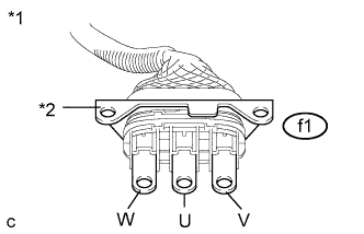
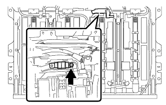
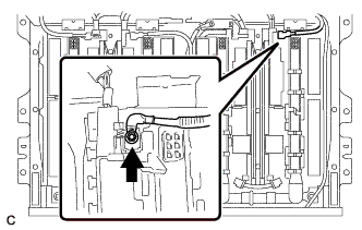
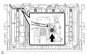
Text in Illustration *1 Generator Cable
(Inverter with Converter Assembly Side)
*2 Shield Ground Using a megohmmeter set to 500 V, measure the resistance according to the value(s) in the table below.
Note
Be sure to set the megohmmeter to 500 V when performing this test. Using a setting higher than 500 V can result in damage to the component being inspected.
Standard Resistance Tester Connection Condition Specified Condition f1-3 (V) - Body ground and shielded wire ground Power switch off 100 MΩ or higher f1-2 (U) - Body ground and shielded wire ground Power switch off 100 MΩ or higher f1-1 (W) - Body ground and shielded wire ground Power switch off 100 MΩ or higher
NG
CHECK GENERATOR CABLE Click here
OK
-
-
CHECK NO. 2 ENGINE WIRE
CAUTION:
Be sure to wear insulated gloves.
-
Check that the service plug grip is not installed.
Note
After removing the service plug grip, do not turn the power switch on (READY), unless instructed by the repair manual because this may cause a malfunction.
-
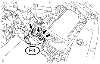
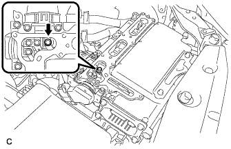
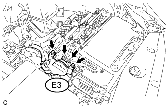
Disconnect connector E3 of the No. 2 engine wire (air conditioning harness) from the inverter with converter assembly.
Tech Tips
Make sure that no foreign matter has entered or contaminated the terminal of the No. 2 engine wire (air conditioning harness) E3.
-
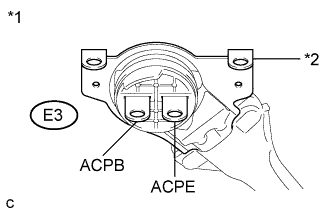
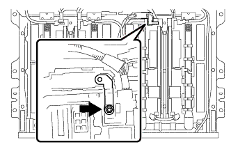
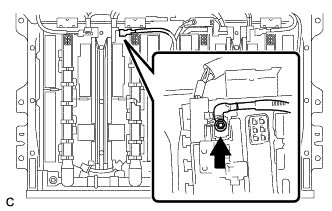
Text in Illustration *1 No. 2 Engine Wire (Air Conditioning Harness)
(Inverter with Converter Assembly Side)
*2 Shield Ground Using a megohmmeter set to 500 V, measure the resistance according to the value(s) in the table below.
Note
Be sure to set the megohmmeter to 500 V when performing this test. Using a setting higher than 500 V can result in damage to the component being inspected.
Standard Resistance Tester Connection Condition Specified Condition E3-1 (ACPB) - Body ground and shielded wire ground Power switch off 3 MΩ or higher E3-2 (ACPE) - Body ground and shielded wire ground Power switch off 3 MΩ or higher
NG
CHECK NO. 2 ENGINE WIRE Click here
OK
-
-
CHECK INVERTER WITH CONVERTER ASSEMBLY
CAUTION:
Be sure to wear insulated gloves.
-
Check that the service plug grip is not installed.
Note
After removing the service plug grip, do not turn the power switch on (READY), unless instructed by the repair manual because this may cause a malfunction.
-
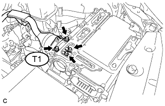
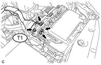
Disconnect connector T1 of the frame wire from the inverter with converter assembly.
Tech Tips
Make sure that no foreign matter has entered or contaminated the terminal of the frame wire T1.
-
Using a megohmmeter set to 500 V, measure the resistance according to the value(s) in the table below.
Note
Be sure to set the megohmmeter to 500 V when performing this test. Using a setting higher than 500 V can result in damage to the component being inspected.
Standard Resistance Tester Connection Condition Specified Condition High voltage terminal - Body ground Power switch off 1 MΩ or higher Tech Tips
Perform this inspection with the motor cable, generator cable and No. 2 engine wire (air conditioning harness) disconnected from the inverter with converter assembly.
NG
REFER TO REPLACE INVERTER WITH CONVERTER ASSEMBLY PARTS Click here
OK
-
-
CHECK FRAME WIRE
CAUTION:
Be sure to wear insulated gloves.
-
Check that the service plug grip is not installed.
Note
After removing the service plug grip, do not turn the power switch on (READY), unless instructed by the repair manual because this may cause a malfunction.
-
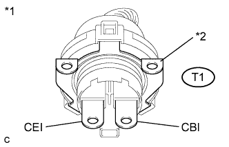
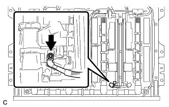
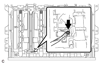
Text in Illustration *1 Frame Wire
(Inverter with Converter Assembly Side)
*2 Shield Ground Using a megohmmeter set to 500 V, measure the resistance according to the value(s) in the table below.
Note
Be sure to set the megohmmeter to 500 V when performing this test. Using a setting higher than 500 V can result in damage to the component being inspected.
Standard Resistance Tester Connection Condition Specified Condition T1-1 (CEI) - Body ground and shielded wire ground Power switch off 10 MΩ or higher T1-2 (CBI) - Body ground and shielded wire ground Power switch off 10 MΩ or higher Tech Tips
Visually inspect the frame wire for damage. If there is any damage, then this is the likely cause of low insulation resistance.
NG
CHECK FRAME WIRE Click here
OK
-
-
CHECK HYBRID BATTERY JUNCTION BLOCK ASSEMBLY
CAUTION:
Be sure to wear insulated gloves.
-
Check that the service plug grip is not installed.
Note
After removing the service plug grip, do not turn the power switch on (READY), unless instructed by the repair manual because this may cause a malfunction.
-
Remove the No. 2 hybrid vehicle battery shield panel Click here.
-
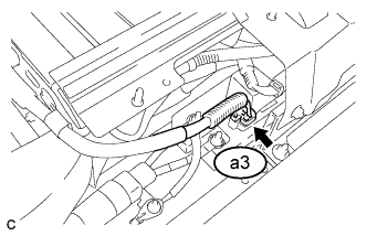
Disconnect connector a3 of the electric vehicle charger wire from the hybrid battery junction block assembly.
-
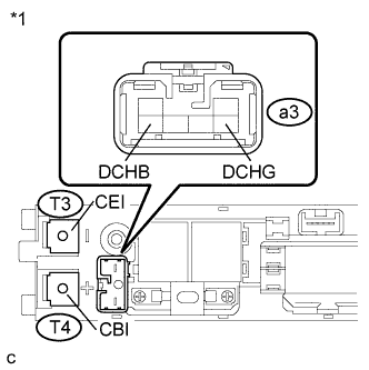
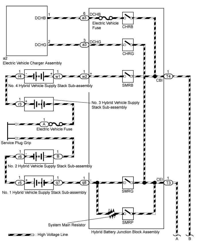
Text in Illustration *1 Hybrid Battery Junction Block Assembly Using a megohmmeter set to 500 V, measure the resistance according to the value(s) in the table below.
Note
Be sure to set the megohmmeter to 500 V when performing this test. Using a setting higher than 500 V can result in damage to the component being inspected.
Standard Resistance Tester Connection Condition Specified Condition a3-6 (DCHB) - Body ground Power switch off 10 MΩ or higher a3-3 (DCHG) - Body ground Power switch off 10 MΩ or higher T4-1 (CBI) - Body ground Power switch off 10 MΩ or higher T3-1 (CEI) - Body ground Power switch off 10 MΩ or higher
NG
REPLACE HYBRID BATTERY JUNCTION BLOCK ASSEMBLY Click here
OK
-
-
CHECK EV CHARGER WIRE
CAUTION:
Be sure to wear insulated gloves.
-
Check that the service plug grip is not installed.
Note
After removing the service plug grip, do not turn the power switch on (READY), unless instructed by the repair manual because this may cause a malfunction.
-
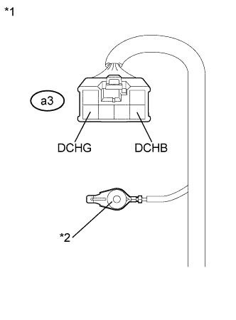
Text in Illustration *1 Electric Vehicle Charger Wire
(Hybrid Battery Junction Block Assembly Side)
*2 Shield Ground Using a megohmmeter set to 500 V, measure the resistance according to the value(s) in the table below.
Note
Be sure to set the megohmmeter to 500 V when performing this test. Using a setting higher than 500 V can result in damage to the component being inspected.
Standard Resistance Tester Connection Condition Specified Condition a3-6 (DCHB) - Body ground and shielded wire ground Power switch off 10 MΩ or higher a3-3 (DCHG) - Body ground and shielded wire ground Power switch off 10 MΩ or higher
NG
CHECK EV CHARGER WIRE Click here
OK
-
-
CHECK HV BATTERY AREA
CAUTION:
Be sure to wear insulated gloves.
-
Check that the service plug grip is not installed.
Note
After removing the service plug grip, do not turn the power switch on (READY), unless instructed by the repair manual because this may cause a malfunction.
-
Remove the No. 1 hybrid vehicle battery shield panel Click here.
-
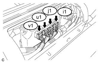
Disconnect the i1, j1, u1 and v1 battery smart unit connectors.
-
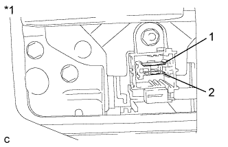
Text in Illustration *1 Electric Vehicle Battery Plug Assembly
(Service Plug Grip Side)
Using a megohmmeter set to 500 V, measure the resistance according to the value(s) in the table below.
Note
Be sure to set the megohmmeter to 500 V when performing this test. Using a setting higher than 500 V can result in damage to the component being inspected.
Standard Resistance Tester Connection Condition Specified Condition 1 - Body ground Power switch off 10 MΩ or higher 2 - Body ground Power switch off 10 MΩ or higher
NG
CHECK HV BATTERY Click here
OK 
REPLACE BATTERY SMART UNIT Click here
-
-
CHECK INVERTER WITH CONVERTER ASSEMBLY
CAUTION:
Be sure to wear insulated gloves.
-
Check that the service plug grip is not installed.
Note
After removing the service plug grip, do not turn the power switch on (READY), unless instructed by the repair manual because this may cause a malfunction.
-
Remove the inverter cover from the inverter with converter assembly.
Tech Tips
Make sure that no foreign matter has entered or contaminated the inverter with converter assembly.
-

Text in Illustration *1 Motor Cable *2 Generator Cable Disconnect connector e1 and f1 of the motor cable and generator cable from the inverter with converter assembly.
-
Using a megohmmeter set to 500 V, measure the resistance according to the value(s) in the table below.
Note
Be sure to set the megohmmeter to 500 V when performing this test. Using a setting higher than 500 V can result in damage to the component being inspected.
Standard Resistance Tester Connection Condition Specified Condition High voltage terminal - Body ground Power switch off 1 MΩ or higher Result Result Proceed to NG A OK B
B
CHECK MOTOR CABLE Click here
A
REFER TO REPLACE INVERTER WITH CONVERTER ASSEMBLY PARTS Click here
-
-
CHECK HIGH VOLTAGE DIRECT CURRENT AREA
CAUTION:
Be sure to wear insulated gloves.
-
Check that the service plug grip is not installed.
Note
After removing the service plug grip, do not turn the power switch on (READY), unless instructed by the repair manual because this may cause a malfunction.
-
Remove the inverter cover from the inverter with converter assembly.
Tech Tips
Make sure that no foreign matter has entered or contaminated the inverter with converter assembly.
-
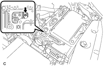
Disconnect connector T1 of the frame wire from the inverter with converter assembly.
Tech Tips
Make sure that no foreign matter has entered or contaminated the terminal of the frame wire T1.
-
Text in Illustration *1 Frame Wire
(Inverter with Converter Assembly Side)
*2 Shield Ground Using a megohmmeter set to 500 V, measure the resistance according to the value(s) in the table below.
Note
Be sure to set the megohmmeter to 500 V when performing this test. Using a setting higher than 500 V can result in damage to the component being inspected.
Standard Resistance Tester Connection Condition Specified Condition T1-1 (CEI) - Body ground and shielded wire ground Power switch off 10 MΩ or higher T1-2 (CBI) - Body ground and shielded wire ground Power switch off 10 MΩ or higher Tech Tips
Visually inspect the frame wire for damage. If there is any damage, then this is the likely cause of low insulation resistance.
NG
CHECK FRAME WIRE Click here
OK
-
-
CHECK HYBRID BATTERY JUNCTION BLOCK ASSEMBLY
CAUTION:
Be sure to wear insulated gloves.
-
Check that the service plug grip is not installed.
Note
After removing the service plug grip, do not turn the power switch on (READY), unless instructed by the repair manual because this may cause a malfunction.
-
Remove the No. 2 hybrid vehicle battery shield panel Click here.
-
Disconnect connector a3 of the electric vehicle charger wire from the hybrid battery junction block assembly.
-
Text in Illustration *1 Hybrid Battery Junction Block Assembly Using a megohmmeter set to 500 V, measure the resistance according to the value(s) in the table below.
Note
Be sure to set the megohmmeter to 500 V when performing this test. Using a setting higher than 500 V can result in damage to the component being inspected.
Standard Resistance Tester Connection Condition Specified Condition a3-6 (DCHB) - Body ground Power switch off 10 MΩ or higher a3-3 (DCHG) - Body ground Power switch off 10 MΩ or higher T4-1 (CBI) - Body ground Power switch off 10 MΩ or higher T3-1 (CEI) - Body ground Power switch off 10 MΩ or higher
NG
REPLACE HYBRID BATTERY JUNCTION BLOCK ASSEMBLY Click here
OK
-
-
CHECK EV CHARGER WIRE
CAUTION:
Be sure to wear insulated gloves.
-
Check that the service plug grip is not installed.
Note
After removing the service plug grip, do not turn the power switch on (READY), unless instructed by the repair manual because this may cause a malfunction.
-
Text in Illustration *1 Electric Vehicle Charger Wire
(Hybrid Battery Junction Block Assembly Side)
*2 Shield Ground Using a megohmmeter set to 500 V, measure the resistance according to the value(s) in the table below.
Note
Be sure to set the megohmmeter to 500 V when performing this test. Using a setting higher than 500 V can result in damage to the component being inspected.
Standard Resistance Tester Connection Condition Specified Condition a3-6 (DCHB) - Body ground and shielded wire ground Power switch off 10 MΩ or higher a3-3 (DCHG) - Body ground and shielded wire ground Power switch off 10 MΩ or higher
NG
CHECK EV CHARGER WIRE Click here
OK
-
-
CHECK NO. 2 ENGINE WIRE
CAUTION:
Be sure to wear insulated gloves.
-
Check that the service plug grip is not installed.
Note
After removing the service plug grip, do not turn the power switch on (READY), unless instructed by the repair manual because this may cause a malfunction.
-
Disconnect connector E3 of the No. 2 engine wire (air conditioning harness) from the inverter with converter assembly.
-
Text in Illustration *1 No. 2 Engine Wire (Air Conditioning Harness)
(Inverter with Converter Assembly Side)
*2 Shield Ground Using a megohmmeter set to 500 V, measure the resistance according to the value(s) in the table below.
Note
Be sure to set the megohmmeter to 500 V when performing this test. Using a setting higher than 500 V can result in damage to the component being inspected.
Standard Resistance Tester Connection Condition Specified Condition E3-1 (ACPB) - Body ground and shielded wire ground Power switch off 3 MΩ or higher E3-2 (ACPE) - Body ground and shielded wire ground Power switch off 3 MΩ or higher
NG
CHECK NO. 2 ENGINE WIRE Click here
OK
REFER TO REPLACE INVERTER WITH CONVERTER ASSEMBLY PARTS Click here
-
-
CHECK NO. 2 ENGINE WIRE
CAUTION:
Be sure to wear insulated gloves.
-
Check that the service plug grip is not installed.
Note
After removing the service plug grip, do not turn the power switch on (READY), unless instructed by the repair manual because this may cause a malfunction.
-
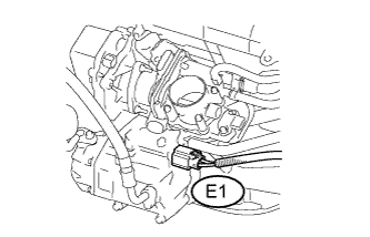
Disconnect connector E1 of the No. 2 engine wire (air conditioning harness) from the compressor with motor assembly Click here.
-
Text in Illustration *1 No. 2 Engine Wire (Air Conditioning Harness)
(Inverter with Converter Assembly Side)
*2 Shield Ground Using a megohmmeter set to 500 V, measure the resistance according to the value(s) in the table below.
Note
Be sure to set the megohmmeter to 500 V when performing this test. Using a setting higher than 500 V can result in damage to the component being inspected.
Standard Resistance Tester Connection Condition Specified Condition E3-1 (ACPB) - Body ground and shielded wire ground Power switch off 10 MΩ or higher E3-2 (ACPE) - Body ground and shielded wire ground Power switch off 10 MΩ or higher
NG
REPLACE NO. 2 ENGINE WIRE
OK
GO TO AIR CONDITIONING SYSTEM (P0AA6-611) Click here
-
-
CHECK EV CHARGER WIRE
CAUTION:
Be sure to wear insulated gloves.
-
Check that the service plug grip is not installed.
Note
After removing the service plug grip, do not turn the power switch on (READY), unless instructed by the repair manual because this may cause a malfunction.
-
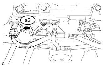
Disconnect connector a2 of the electric vehicle charger wire from the electric vehicle charger assembly Click here.
-
Text in Illustration *1 Electric Vehicle Charger Wire
(Hybrid Battery Junction Block Assembly Side)
*2 Shield Ground Using a megohmmeter set to 500 V, measure the resistance according to the value(s) in the table below.
Note
Be sure to set the megohmmeter to 500 V when performing this test. Using a setting higher than 500 V can result in damage to the component being inspected.
Standard Resistance Tester Connection Condition Specified Condition a3-6 (DCHB) - Body ground and shielded wire ground Power switch off 10 MΩ or higher a3-3 (DCHG) - Body ground and shielded wire ground Power switch off 10 MΩ or higher
NG
REPLACE EV CHARGER WIRE Click here
OK
REPLACE ELECTRIC VEHICLE CHARGER ASSEMBLY Click here
-
-
CHECK FRAME WIRE
CAUTION:
Be sure to wear insulated gloves.
-
Check that the service plug grip is not installed.
Note
After removing the service plug grip, do not turn the power switch on (READY), unless instructed by the repair manual because this may cause a malfunction.
-
Remove the No. 2 hybrid vehicle battery shield panel Click here.
-
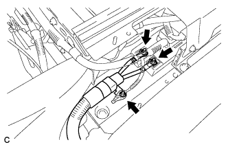
Disconnect the frame wire from the hybrid battery junction block assembly.
-
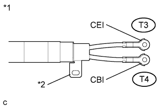
Text in Illustration *1 Frame Wire
(Hybrid Battery Junction Block Assembly Side)
*2 Shield Ground Using a megohmmeter set to 500 V, measure the resistance according to the value(s) in the table below.
Note
Be sure to set the megohmmeter to 500 V when performing this test. Using a setting higher than 500 V can result in damage to the component being inspected.
Standard Resistance Tester Connection Condition Specified Condition T3-1 (CEI) - Body ground and shielded wire ground Power switch off 10 MΩ or higher T4-1 (CBI) - Body ground and shielded wire ground Power switch off 10 MΩ or higher Tech Tips
Visually inspect the frame wire for damage. If there is any damage, then this is the likely cause of low insulation resistance.
NG
REPLACE FRAME WIRE Click here
OK
REPLACE HYBRID BATTERY JUNCTION BLOCK ASSEMBLY Click here
-
-
CHECK HV BATTERY
CAUTION:
Be sure to wear insulated gloves.
-
Check that the service plug grip is not installed.
Note
After removing the service plug grip, do not turn the power switch on (READY), unless instructed by the repair manual because this may cause a malfunction.
-
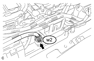
Disconnect connector of the No. 2 hybrid vehicle battery pack cable from the hybrid battery junction block assembly.
-
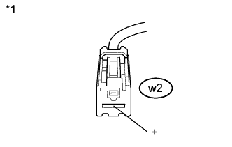
Text in Illustration *1 No. 2 Hybrid Vehicle Battery Pack Cable
(Hybrid Battery Junction Block Assembly Side)
Using a megohmmeter set to 500 V, measure the resistance according to the value(s) in the table below.
Note
Be sure to set the megohmmeter to 500 V when performing this test. Using a setting higher than 500 V can result in damage to the component being inspected.
Standard Resistance Tester Connection Condition Specified Condition w2-1 (+) - Body ground Power switch off 10 MΩ or higher
NG
CHECK HV BATTERY Click here
OK
-
-
CHECK HV BATTERY
CAUTION:
Be sure to wear insulated gloves.
-
Check that the service plug grip is not installed.
Note
After removing the service plug grip, do not turn the power switch on (READY), unless instructed by the repair manual because this may cause a malfunction.
-
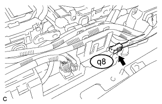
Disconnect connector q8 of the No. 1 hybrid vehicle battery pack cable from the hybrid battery junction block assembly.
-
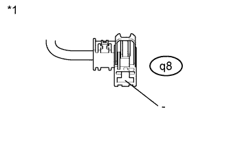
Text in Illustration *1 No. 1 Hybrid Vehicle Battery Pack Cable
(Hybrid Battery Junction Block Assembly Side)
Using a megohmmeter set to 500 V, measure the resistance according to the value(s) in the table below.
Note
Be sure to set the megohmmeter to 500 V when performing this test. Using a setting higher than 500 V can result in damage to the component being inspected.
Standard Resistance Tester Connection Condition Specified Condition q8-1 (-) - Body ground Power switch off 10 MΩ or higher
NG
CHECK HV BATTERY Click here
OK
REPLACE HYBRID BATTERY JUNCTION BLOCK ASSEMBLY Click here
-
-
CHECK HV BATTERY
CAUTION:
Be sure to wear insulated gloves and protective goggles.
-
Check that the service plug grip is not installed.
Note
After removing the service plug grip, do not turn the power switch on (READY), unless instructed by the repair manual because this may cause a malfunction.
-
Remove the upper hybrid battery cover sub-assembly Click here.
-
Disconnect the electric vehicle battery plug assembly from the electric vehicle fuse.
-
Text in Illustration *1 No. 2 Hybrid Vehicle Battery Pack Cable
(Hybrid Battery Junction Block Assembly Side)
Using a megohmmeter set to 500 V, measure the resistance according to the value(s) in the table below.
Note
Be sure to set the megohmmeter to 500 V when performing this test. Using a setting higher than 500 V can result in damage to the component being inspected.
Standard Resistance Tester Connection Condition Specified Condition w2-1 (+) - Body ground Power switch off 10 MΩ or higher
NG
CHECK HV BATTERY Click here
OK
REPLACE ELECTRIC VEHICLE BATTERY PLUG ASSEMBLY Click here
-
-
CHECK HV BATTERY
CAUTION:
Be sure to wear insulated gloves and protective goggles.
-
Check that the service plug grip is not installed.
Note
After removing the service plug grip, do not turn the power switch on (READY), unless instructed by the repair manual because this may cause a malfunction.
-
Remove the electric vehicle fuse.
-
Text in Illustration *1 No. 2 Hybrid Vehicle Battery Pack Cable
(Hybrid Battery Junction Block Assembly Side)
Using a megohmmeter set to 500 V, measure the resistance according to the value(s) in the table below.
Note
Be sure to set the megohmmeter to 500 V when performing this test. Using a setting higher than 500 V can result in damage to the component being inspected.
Standard Resistance Tester Connection Condition Specified Condition w2-1 (+) - Body ground Power switch off 10 MΩ or higher
NG
CHECK HV BATTERY Click here
OK
REPLACE ELECTRIC VEHICLE FUSE Click here
-
-
CHECK HV BATTERY
CAUTION:
Be sure to wear insulated gloves and protective goggles.
-
Check that the service plug grip is not installed.
Note
After removing the service plug grip, do not turn the power switch on (READY), unless instructed by the repair manual because this may cause a malfunction.
-
Remove the No. 6 hybrid vehicle battery terminal.
-
Text in Illustration *1 No. 2 Hybrid Vehicle Battery Pack Cable
(Hybrid Battery Junction Block Assembly Side)
Using a megohmmeter set to 500 V, measure the resistance according to the value(s) in the table below.
Note
Be sure to set the megohmmeter to 500 V when performing this test. Using a setting higher than 500 V can result in damage to the component being inspected.
Standard Resistance Tester Connection Condition Specified Condition w2-1 (+) - Body ground Power switch off 10 MΩ or higher
NG
CHECK HV BATTERY Click here
OK
REPLACE NO. 6 HYBRID VEHICLE BATTERY TERMINAL Click here
-
-
CHECK HV BATTERY
CAUTION:
Be sure to wear insulated gloves and protective goggles.
-
Check that the service plug grip is not installed.
Note
After removing the service plug grip, do not turn the power switch on (READY), unless instructed by the repair manual because this may cause a malfunction.
-
Disconnect the No. 3 hybrid vehicle battery pack cable from the No. 3 hybrid vehicle supply stack sub-assembly.
-
Text in Illustration *1 No. 2 Hybrid Vehicle Battery Pack Cable
(Hybrid Battery Junction Block Assembly Side)
Using a megohmmeter set to 500 V, measure the resistance according to the value(s) in the table below.
Note
-
Be sure to set the megohmmeter to 500 V when performing this test. Using a setting higher than 500 V can result in damage to the component being inspected.
-
Wrap insulating tape around the terminal of the No. 3 hybrid vehicle battery pack cable on the No. 3 hybrid vehicle supply stack sub-assembly side to prevent it from contacting the body ground.
Standard Resistance Tester Connection Condition Specified Condition w2-1 (+) - Body ground Power switch off 10 MΩ or higher -
NG
CHECK HV BATTERY Click here
OK
REPLACE NO. 3 HYBRID VEHICLE SUPPLY STACK SUB-ASSEMBLY Click here
-
-
CHECK HV BATTERY
CAUTION:
Be sure to wear insulated gloves and protective goggles.
-
Check that the service plug grip is not installed.
Note
After removing the service plug grip, do not turn the power switch on (READY), unless instructed by the repair manual because this may cause a malfunction.
-
Disconnect the No. 3 hybrid vehicle battery pack cable from the No. 4 hybrid vehicle supply stack sub-assembly.
-
Text in Illustration *1 No. 2 Hybrid Vehicle Battery Pack Cable
(Hybrid Battery Junction Block Assembly Side)
Using a megohmmeter set to 500 V, measure the resistance according to the value(s) in the table below.
Note
Be sure to set the megohmmeter to 500 V when performing this test. Using a setting higher than 500 V can result in damage to the component being inspected.
Standard Resistance Tester Connection Condition Specified Condition w2-1 (+) - Body ground Power switch off 10 MΩ or higher
NG
CHECK NO. 2 HYBRID VEHICLE BATTERY PACK CABLE Click here
OK
REPLACE NO. 3 HYBRID VEHICLE BATTERY PACK CABLE (NO. 3 HYBRID VEHICLE SUPPLY STACK - NO. 4 HYBRID VEHICLE SUPPLY STACK) Click here
-
-
CHECK NO. 2 HYBRID VEHICLE BATTERY PACK CABLE
CAUTION:
Be sure to wear insulated gloves and protective goggles.
-
Check that the service plug grip is not installed.
Note
After removing the service plug grip, do not turn the power switch on (READY), unless instructed by the repair manual because this may cause a malfunction.
-
Disconnect the No. 2 hybrid vehicle battery pack cable from the No. 4 hybrid vehicle supply stack sub-assembly.
-
Text in Illustration *1 No. 2 Hybrid Vehicle Battery Pack Cable
(Hybrid Battery Junction Block Assembly Side)
Using a megohmmeter set to 500 V, measure the resistance according to the value(s) in the table below.
Note
-
Be sure to set the megohmmeter to 500 V when performing this test. Using a setting higher than 500 V can result in damage to the component being inspected.
-
Wrap insulating tape around the terminal of the No. 2 hybrid vehicle battery pack cable on the No. 4 hybrid vehicle supply stack sub-assembly side to prevent it from contacting the body ground.
Standard Resistance Tester Connection Condition Specified Condition w2-1 (+) - Body ground Power switch off 10 MΩ or higher -
NG
REPLACE NO. 2 HYBRID VEHICLE BATTERY PACK CABLE Click here
OK
REPLACE NO. 4 HYBRID VEHICLE SUPPLY STACK SUB-ASSEMBLY Click here
-
-
CHECK HV BATTERY
CAUTION:
Be sure to wear insulated gloves and protective goggles.
-
Check that the service plug grip is not installed.
Note
After removing the service plug grip, do not turn the power switch on (READY), unless instructed by the repair manual because this may cause a malfunction.
-
Remove the upper hybrid battery cover sub-assembly Click here.
-
Disconnect the electric vehicle battery plug assembly from the No. 2 hybrid vehicle supply stack sub-assembly.
-
Text in Illustration *1 No. 1 Hybrid Vehicle Battery Pack Cable
(Hybrid Battery Junction Block Assembly Side)
Using a megohmmeter set to 500 V, measure the resistance according to the value(s) in the table below.
Note
Be sure to set the megohmmeter to 500 V when performing this test. Using a setting higher than 500 V can result in damage to the component being inspected.
Standard Resistance Tester Connection Condition Specified Condition q8-1 (-) - Body ground Power switch off 10 MΩ or higher
NG
CHECK HV BATTERY Click here
OK
REPLACE ELECTRIC VEHICLE BATTERY PLUG ASSEMBLY Click here
-
-
CHECK HV BATTERY
CAUTION:
Be sure to wear insulated gloves and protective goggles.
-
Check that the service plug grip is not installed.
Note
After removing the service plug grip, do not turn the power switch on (READY), unless instructed by the repair manual because this may cause a malfunction.
-
Disconnect the No. 3 hybrid vehicle battery pack cable from the No. 2 hybrid vehicle supply stack sub-assembly.
-
Text in Illustration *1 No. 1 Hybrid Vehicle Battery Pack Cable
(Hybrid Battery Junction Block Assembly Side)
Using a megohmmeter set to 500 V, measure the resistance according to the value(s) in the table below.
Note
-
Be sure to set the megohmmeter to 500 V when performing this test. Using a setting higher than 500 V can result in damage to the component being inspected.
-
Wrap insulating tape around the terminal of the No. 3 hybrid vehicle battery pack cable on the No. 2 hybrid vehicle supply stack sub-assembly side to prevent it from contacting the body ground.
Standard Resistance Tester Connection Condition Specified Condition q8-1 (-) - Body ground Power switch off 10 MΩ or higher -
NG
CHECK HV BATTERY Click here
OK
REPLACE NO. 2 HYBRID VEHICLE SUPPLY STACK SUB-ASSEMBLY Click here
-
-
CHECK HV BATTERY
CAUTION:
Be sure to wear insulated gloves and protective goggles.
-
Check that the service plug grip is not installed.
Note
After removing the service plug grip, do not turn the power switch on (READY), unless instructed by the repair manual because this may cause a malfunction.
-
Disconnect the No. 3 hybrid vehicle battery pack cable from the No. 1 hybrid vehicle supply stack sub-assembly.
-
Text in Illustration *1 No. 1 Hybrid Vehicle Battery Pack Cable
(Hybrid Battery Junction Block Assembly Side)
Using a megohmmeter set to 500 V, measure the resistance according to the value(s) in the table below.
Note
Be sure to set the megohmmeter to 500 V when performing this test. Using a setting higher than 500 V can result in damage to the component being inspected.
Standard Resistance Tester Connection Condition Specified Condition q8-1 (-) - Body ground Power switch off 10 MΩ or higher
NG
CHECK NO. 1 HYBRID VEHICLE BATTERY PACK CABLE Click here
OK
REPLACE NO. 3 HYBRID VEHICLE BATTERY PACK CABLE (NO. 1 HYBRID VEHICLE SUPPLY STACK - NO. 2 HYBRID VEHICLE SUPPLY STACK) Click here
-
-
CHECK NO. 1 HYBRID VEHICLE BATTERY PACK CABLE
CAUTION:
Be sure to wear insulated gloves and protective goggles.
-
Check that the service plug grip is not installed.
Note
After removing the service plug grip, do not turn the power switch on (READY), unless instructed by the repair manual because this may cause a malfunction.
-
Disconnect the No. 1 hybrid vehicle battery pack cable from the No. 1 hybrid vehicle supply stack sub-assembly.
-
Text in Illustration *1 No. 1 Hybrid Vehicle Battery Pack Cable
(Hybrid Battery Junction Block Assembly Side)
Using a megohmmeter set to 500 V, measure the resistance according to the value(s) in the table below.
Note
-
Be sure to set the megohmmeter to 500 V when performing this test. Using a setting higher than 500 V can result in damage to the component being inspected.
-
Wrap insulating tape around the terminal of the No. 1 hybrid vehicle battery pack cable on the No. 1 hybrid vehicle supply stack sub-assembly side to prevent it from contacting the body ground.
Standard Resistance Tester Connection Condition Specified Condition q8-1 (-) - Body ground Power switch off 10 MΩ or higher -
NG
REPLACE NO. 1 HYBRID VEHICLE BATTERY PACK CABLE Click here
OK
REPLACE NO. 1 HYBRID VEHICLE SUPPLY STACK SUB-ASSEMBLY Click here
-
-
CHECK MOTOR CABLE
CAUTION:
Be sure to wear insulated gloves.
-
Check that the service plug grip is not installed.
Note
After removing the service plug grip, do not turn the power switch on (READY), unless instructed by the repair manual because this may cause a malfunction.
-
Disconnect the motor cable from the hybrid vehicle transaxle assembly Click here.
-
Text in Illustration *1 Motor Cable
(Inverter with Converter Assembly Side)
*2 Shield Ground Using a megohmmeter set to 500 V, measure the resistance according to the value(s) in the table below.
Note
Be sure to set the megohmmeter to 500 V when performing this test. Using a setting higher than 500 V can result in damage to the component being inspected.
Standard Resistance Tester Connection Condition Specified Condition e1-2 (U) - Body ground and shielded wire ground Power switch off 100 MΩ or higher e1-3 (V) - Body ground and shielded wire ground Power switch off 100 MΩ or higher e1-1 (W) - Body ground and shielded wire ground Power switch off 100 MΩ or higher
NG
REPLACE MOTOR CABLE Click here
OK
REPLACE HYBRID VEHICLE TRANSAXLE ASSEMBLY Click here
-
-
CHECK GENERATOR CABLE
CAUTION:
Be sure to wear insulated gloves.
-
Check that the service plug grip is not installed.
Note
After removing the service plug grip, do not turn the power switch on (READY), unless instructed by the repair manual because this may cause a malfunction.
-
Disconnect the generator cable from the hybrid vehicle transaxle assembly Click here.
-
Text in Illustration *1 Generator Cable
(Inverter with Converter Assembly Side)
*2 Shield Ground Using a megohmmeter set to 500 V, measure the resistance according to the value(s) in the table below.
Note
Be sure to set the megohmmeter to 500 V when performing this test. Using a setting higher than 500 V can result in damage to the component being inspected.
Standard Resistance Tester Connection Condition Specified Condition f1-3 (V) - Body ground and shielded wire ground Power switch off 100 MΩ or higher f1-2 (U) - Body ground and shielded wire ground Power switch off 100 MΩ or higher f1-1 (W) - Body ground and shielded wire ground Power switch off 100 MΩ or higher
NG
REPLACE GENERATOR CABLE Click here
OK
REPLACE HYBRID VEHICLE TRANSAXLE ASSEMBLY Click here
-
-
CHECK MOTOR CABLE
CAUTION:
Be sure to wear insulated gloves.
-
Check that the service plug grip is not installed.
Note
After removing the service plug grip, do not turn the power switch on (READY), unless instructed by the repair manual because this may cause a malfunction.
-
Disconnect the motor cable from the hybrid vehicle transaxle assembly Click here.
-
Text in Illustration *1 Motor Cable
(Inverter with Converter Assembly Side)
*2 Shield Ground Using a megohmmeter set to 500 V, measure the resistance according to the value(s) in the table below.
Note
Be sure to set the megohmmeter to 500 V when performing this test. Using a setting higher than 500 V can result in damage to the component being inspected.
Standard Resistance Tester Connection Condition Specified Condition e1-2 (U) - Body ground and shielded wire ground Power switch off 100 MΩ or higher e1-3 (V) - Body ground and shielded wire ground Power switch off 100 MΩ or higher e1-1 (W) - Body ground and shielded wire ground Power switch off 100 MΩ or higher
NG
REPLACE MOTOR CABLE Click here
OK
-
-
CHECK GENERATOR CABLE
CAUTION:
Be sure to wear insulated gloves.
-
Check that the service plug grip is not installed.
Note
After removing the service plug grip, do not turn the power switch on (READY), unless instructed by the repair manual because this may cause a malfunction.
-
Disconnect the generator cable from the hybrid vehicle transaxle assembly Click here.
-
Text in Illustration *1 Generator Cable
(Inverter with Converter Assembly Side)
*2 Shield Ground Using a megohmmeter set to 500 V, measure the resistance according to the value(s) in the table below.
Note
Be sure to set the megohmmeter to 500 V when performing this test. Using a setting higher than 500 V can result in damage to the component being inspected.
Standard Resistance Tester Connection Condition Specified Condition f1-3 (V) - Body ground and shielded wire ground Power switch off 100 MΩ or higher f1-2 (U) - Body ground and shielded wire ground Power switch off 100 MΩ or higher f1-1 (W) - Body ground and shielded wire ground Power switch off 100 MΩ or higher
NG
REPLACE GENERATOR CABLE Click here
OK
REPLACE HYBRID VEHICLE TRANSAXLE ASSEMBLY Click here
-