HYBRID CONTROL SYSTEM, Diagnostic DTC:P0A78-282
| DTC Code | DTC Name |
|---|---|
| P0A78-282 | Drive Motor "A" Inverter Performance |
DESCRIPTION
For a description of the inverter Click here.
If an overvoltage occurs in the motor inverter or generator inverter, the MG ECU detects it and transmits this information to the power management control ECU.
| DTC No. | INF Code | DTC Detection Condition | Trouble Area |
|---|---|---|---|
| P0A78 | 282 | Motor inverter overvoltage signal detection (circuit malfunction) | Inverter with converter assembly |
INSPECTION PROCEDURE
CAUTION:
-
Before inspecting the high-voltage system or disconnecting the low voltage connector of the inverter with converter assembly or electric vehicle charger assembly, turn the power switch off. Also, take safety precautions such as wearing insulated gloves and removing the service plug grip to prevent electrical shocks. After removing the service plug grip, put it in your pocket to prevent other technicians from accidentally reconnecting it while you are working on the high-voltage system.
-
After removing the service plug grip, wait for at least 10 minutes before touching any of the high-voltage connectors or terminals. After waiting for 10 minutes, check the voltage at the terminals in the inspection point in the inverter with converter assembly. The voltage should be 0 V before beginning work Click here.
Tech Tips
Waiting for at least 10 minutes is required to discharge the high-voltage capacitor inside the inverter with converter assembly and electric vehicle charger assembly.
Note
After turning the power switch off, waiting time may be required before disconnecting the cable from the negative (-) auxiliary battery terminal. Therefore, make sure to read the disconnecting the cable from the negative (-) auxiliary battery terminal notices before proceeding with work Click here.
PROCEDURE
-
CHECK DTC OUTPUT (HYBRID CONTROL)
-
Connect the GTS to the DLC3.
-
Turn the power switch on (IG).
-
Enter the following menus: Powertrain / Hybrid Control / Trouble Codes.
-
Check if DTCs are output.
Result Result Proceed to Only P0A78-282 is output, or DTCs other than the ones in the table below are also output. A Any of the DTCs including pending DTCs are also output. B DTC No. Relevant Diagnosis P1A61-123 Hybrid Battery Cell Low Voltage Stack "B" P1A64-123 Hybrid Battery Cell Low Voltage Stack "C" P1A67-123 Hybrid Battery Cell Low Voltage Stack "D" P31AB-123 Hybrid Battery Cell Low Voltage Tech Tips
Only P0A78-282 may be set due to a malfunction which also causes DTCs in the preceding table to be set. In this case, first troubleshoot the output DTCs in the preceding table. Then, perform a test to attempt to reproduce the problems, and check that no DTCs are output.
-
Turn the power switch off.
B 
GO TO DTC CHART (HYBRID BATTERY SYSTEM) Click here
A 
-
-
CHECK DTC OUTPUT (HYBRID CONTROL)
-
Connect the GTS to the DLC3.
-
Turn the power switch on (IG).
-
Enter the following menus: Powertrain / Hybrid Control / Trouble Codes.
-
Check if DTCs are output.
Result Result Proceed to P0A78-282 is set before any of the DTCs in the table below are set. A Any of the DTCs in the table 1 below are set before P0A78-282 is set. B Any of the DTCs in the table 2 below are set before P0A78-282 is set. C Table 1 DTC No. Relevant Diagnosis P3000-388, 389, 603 Hybrid Battery Malfunction P3004-131, 133 Power Cable Malfunction Table 2 DTC No. Relevant Diagnosis P31B4-123 Extreme Charging Current Caused by HV Battery High Voltage Tech Tips
P0A78-282 may be set due to a malfunction which also causes DTCs in the preceding table to be set. In this case, first troubleshoot the output DTCs in the preceding table. Then, perform a test to attempt to reproduce the problems, and check that no DTCs are output.
-
Turn the power switch off.
B
GO TO DTC CHART (HYBRID CONTROL SYSTEM) Click here
C
GO TO DTC CHART (HYBRID BATTERY SYSTEM) Click here
A
-
-
CHECK CONNECTOR CONNECTION CONDITION (INVERTER WITH CONVERTER ASSEMBLY CONNECTOR)
CAUTION:
Be sure to wear insulated gloves.
-
Check that the service plug grip is not installed.
Note
After removing the service plug grip, do not turn the power switch on (READY), unless instructed by the repair manual because this may cause a malfunction.
Note
Before disconnecting the connector, confirm that it is properly connected by checking that the locking claws are engaged and that the connector does not pull out.
-
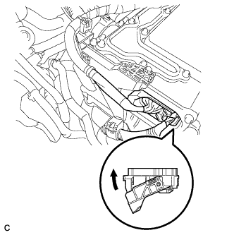
Check the connection of the low voltage connector of the inverter with converter assembly.
OK The connector is connected securely and there are no contact problems. Tech Tips
When connecting the connector, insert it with the locking lever in the raised position. Rotate the lever downward and make sure that the connector is pulled into its socket. When the locking lever is in its fully closed position, a click will be heard as its locking claws engage. After the click is heard, pull up on the connector to confirm that it is properly connected.
NG
CONNECT SECURELY
OK 
REFER TO REPLACE INVERTER WITH CONVERTER ASSEMBLY PARTS Click here
-