HYBRID CONTROL SYSTEM, Diagnostic DTC:P0C30-390
| DTC Code | DTC Name |
|---|---|
| P0C30-390 | Hybrid Battery Pack State of Charge High |
DESCRIPTION
The Power management control ECU monitors its internal operation, it will set DTCs and perform fail-safe control when it detects the following malfunctions.
| DTC No. | INF Code | DTC Detection Condition | Trouble Area |
|---|---|---|---|
| P0C30 | 390 | Charge control error |
|
INSPECTION PROCEDURE
CAUTION:
-
When performing P0C30-390 troubleshooting, use either a tool wrapped with vinyl insulation tape or a insulated tool. (It is extremely dangerous when a high-voltage charge passes through a non-insulated tool causing a short.)
-
Before inspecting the high-voltage system or disconnecting the low voltage connector of the inverter with converter assembly or electric vehicle charger assembly, turn the power switch off. Also, take safety precautions such as wearing insulated gloves and removing the service plug grip to prevent electrical shocks. After removing the service plug grip, put it in your pocket to prevent other technicians from accidentally reconnecting it while you are working on the high-voltage system.
-
After removing the service plug grip, wait for at least 10 minutes before touching any of the high-voltage connectors or terminals. After waiting for 10 minutes, check the voltage at the terminals in the inspection point in the inverter with converter assembly. The voltage should be 0 V before beginning work Click here.
Tech Tips
Waiting for at least 10 minutes is required to discharge the high-voltage capacitor inside the inverter with converter assembly and electric vehicle charger assembly.
Note
After turning the power switch off, waiting time may be required before disconnecting the cable from the negative (-) auxiliary battery terminal. Therefore, make sure to read the disconnecting the cable from the negative (-) auxiliary battery terminal notices before proceeding with work Click here.
PROCEDURE
-
CHECK DTC OUTPUT (HYBRID CONTROL)
-
Connect the GTS to the DLC3.
-
Turn the power switch on (IG).
-
Enter the following menus: Powertrain / Hybrid Control / Trouble Codes.
-
Check if DTCs are output.
Result Result Proceed to P0C30-390 only is output. A DTCs other than P0C30-390 are output. B -
Turn the power switch off.
B 
GO TO DTC CHART (HYBRID CONTROL SYSTEM) Click here
A 
-
-
CHECK FREEZE FRAME DATA
-
Connect the GTS to the DLC3.
-
Turn the power switch on (IG).
-
Enter the following menus: Powertrain / Hybrid Control / Trouble Codes.
-
Read the freeze frame data of DTC P0C30-390.
Result Result Proceed to OFF is displayed for "Ready Signal", "SMRP Status", "SMRB Status" and "SMRG Status" and -0.5 A or less is displayed for "Power Resource IB" for all of the Data List items. A Other than above B Tech Tips
As the power switch on (IG) state may cause the DTC to be stored, freeze frame data is used to judge the cause of the DTC output.
-
Turn the power switch off.
B
REPLACE POWER MANAGEMENT CONTROL ECU Click here
A
-
-
CHECK HYBRID BATTERY JUNCTION BLOCK ASSEMBLY (SMRP, SMRB, SMRG)
CAUTION:
Be sure to wear insulated gloves.
-
Check that the service plug grip is not installed.
Note
After removing the service plug grip, do not turn the power switch on (READY), unless instructed by the repair manual because this may cause a malfunction.
-
Remove the No. 1 hybrid vehicle battery shield panel Click here.
-
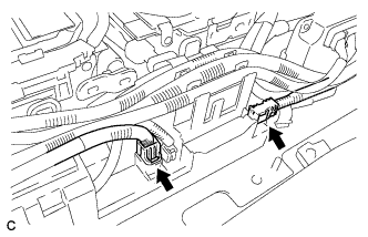
Disconnect the HV battery high voltage connectors from the hybrid battery junction block assembly.
-
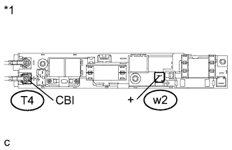
Text in Illustration *1 Hybrid Battery Junction Block Assembly Measure the resistance according to the value(s) in the table below.
Standard Resistance (SMRB) Tester Connection Condition Specified Condition T4-1(CBI) - w2-1(+) Power switch off 10 kΩ or higher Tech Tips
If a system main relay is stuck closed, inspect the hybrid battery junction block assembly without removing it from the vehicle, in order to keep the relay closed.
-
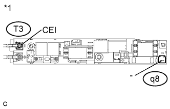
Text in Illustration *1 Hybrid Battery Junction Block Assembly Measure the resistance according to the value(s) in the table below.
Standard Resistance (SMRG, SMRP) Tester Connection Condition Specified Condition T3-1(CEI) - q8-1(-) Power switch off 10 kΩ or higher Tech Tips
-
If a system main relay is stuck closed, inspect the hybrid battery junction block assembly without removing it from the vehicle, in order to keep the relay closed.
-
If the resistance is between 28.5 and 31.5 Ω, it can be determined that SMRP is stuck closed.
-
-
Connect the HV battery high voltage connectors.
-
Install the No. 1 hybrid vehicle battery shield panel.
NG
REPLACE HYBRID BATTERY JUNCTION BLOCK ASSEMBLY Click here
OK
-
-
PERFORM INITIALIZATION (CURRENT SENSOR OFFSET LEARNING)
-
Connect the GTS to the DLC3.
-
Turn the power switch on (READY).
-
Perform a road test.
Note
Accelerate/decelerate gently. Avoid rapid acceleration/deceleration.
-
Enter the following menus: Powertrain / Hybrid Control / Data List / Power Resource IB.
-
Drive the vehicle with the value of Data List item "Power Resource IB" between -50 A and 50 A.
Tech Tips
Distance and driving time are not specified.
-
-
Turn the power switch off and leave the vehicle for 30 seconds or more.
-
Turn the power switch on (IG).
-
Enter the following menus: Powertrain / Hybrid Control / Data List / Power Resource IB.
-
Check that the value of "Power Resource IB" is between - 0.5 A and 0.5 A with the power switch on (IG).
Note
If the value is outside the specified range, perform the road test again.
Tech Tips
-
If the power switch is on (IG) and value of "Power Resource IB" is between - 0.5 A and 0.5 A, current sensor offset learning has been completed.
-
Even if the current sensor offset learning is not complete, the current sensor value will be corrected by repeating the road test a maximum of 7 times.
-
NEXT 
COMPLETED
-