POWER STEERING SYSTEM EPS Warning Light Circuit
DESCRIPTION
If the power steering ECU assembly detects a malfunction, the EPS warning light comes on. At this time, the power steering ECU assembly stores a DTC in its memory.
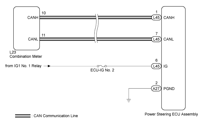
WIRING DIAGRAM
INSPECTION PROCEDURE
Note
If the power steering ECU assembly has been replaced with a new one, perform assist map writing and rotation angle sensor value initialization torque sensor zero point calibration after performing the initialization of the torque sensor zero point value Click here.
Tech Tips
Inspect the fuses for circuits related to this system before performing the following inspection procedure.
PROCEDURE
-
CHECK FOR DTC (CAN COMMUNICATION SYSTEM)
-
Check for DTCs Click here.
OK DTC is not output.
NG 
GO TO CAN COMMUNICATION SYSTEM Click here
OK 
-
-
CHECK HARNESS AND CONNECTOR (POWER STEERING ECU ASSEMBLY - BODY GROUND)
-
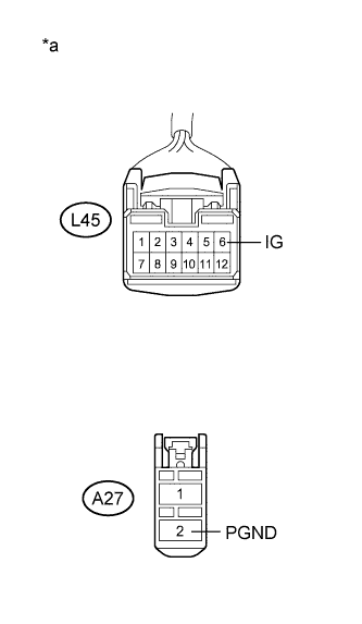
Text in Illustration *a Front view of wire harness connector
(to Power Steering ECU Assembly)
Disconnect the L45 and A27 power steering ECU assembly connectors.
-
Measure the voltage according to the value(s) in the table below.
Standard Voltage Tester Connection Condition Specified Condition L45-6 (IG) - Body ground Power switch on (IG) 9 to 16 V -
Measure the resistance according to the value(s) in the table below.
Standard Resistance Tester Connection Condition Specified Condition A27-2 (PGND) - Body ground Always Below 1 Ω
NG
REPAIR OR REPLACE HARNESS OR CONNECTOR
OK
-
-
INSPECT COMBINATION METER
-
Reconnect the L45 and A27 power steering ECU assembly connectors.
-
Perform the Active Test of the combination meter using the GTS Click here.
-
Check the combination meter.
OK The EPS warning light turns on or off in accordance with the GTS operation. Tech Tips
If troubleshooting has been carried out according to Problem Symptoms Table, refer back to the table and proceed to the next step before replacing the part Click here.
NG
REPLACE NO. 3 METER CIRCUIT PLATE Click here
OK 
REPLACE POWER STEERING ECU ASSEMBLY Click here
-