BRAKE PEDAL (for RHD) REMOVAL
-
REMOVE UPPER INSTRUMENT PANEL ASSEMBLY
-
REMOVE NO. 1 INSTRUMENT PANEL UNDER COVER SUB-ASSEMBLY
-
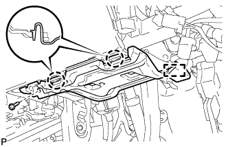
Remove the screw <D>.
-
Disengage the 2 claws and guide.
-
Disconnect each connector and remove the No. 1 instrument panel under cover sub-assembly.
-
-
REMOVE ECU INTEGRATION BOX RH
-
Disconnect the connectors from the ECU integration box RH.
-
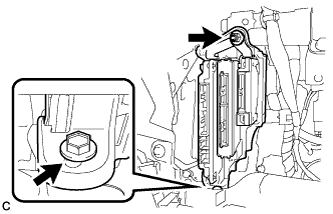
Remove the bolt, nut and ECU integration box RH.
-
-
REMOVE BRAKE PEDAL STROKE SENSOR ASSEMBLY
-
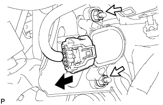
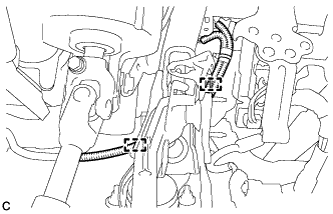
Disconnect the connector from the brake pedal stroke sensor assembly.
-
Remove the 2 nuts and brake pedal stroke sensor assembly.
Note
-
Do not drop the brake pedal stroke sensor assembly.
-
If the brake pedal stroke sensor assembly has been dropped, replace the brake pedal stroke sensor assembly with a new one.
-
-
-
REMOVE STOP LIGHT SWITCH ASSEMBLY
-
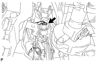
Disconnect the connector.
-
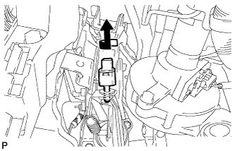
Turn the stop light switch assembly counterclockwise and remove it.
-
-
REMOVE STOP LIGHT SWITCH MOUNTING ADJUSTER
-
REMOVE BRAKE PEDAL RETURN SPRING
-
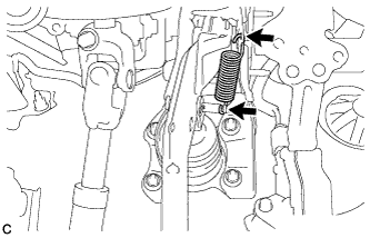
Remove the brake pedal return spring from the brake pedal support assembly and push rod pin.
-
-
REMOVE PUSH ROD PIN
-
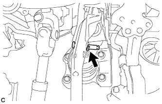
Remove the clip and push rod pin to separate the brake pedal support assembly from the push rod clevis.
-
-
REMOVE BRAKE PEDAL SUPPORT ASSEMBLY
-
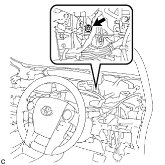
Remove the bolt and separate the brake pedal support assembly from the instrument panel reinforcement.
-
Disengage the 2 clamps.
-
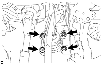
Remove the 4 nuts and brake pedal support assembly.
-
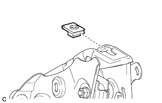
Remove the nut from the brake pedal support assembly.
-