BRAKE PEDAL STROKE SENSOR (for RHD) REMOVAL
Note
While the auxiliary battery is connected, even if the power switch is off, the brake control system activates when the brake pedal is depressed or any door courtesy switch turns on. Therefore, when servicing the brake system components, do not operate the brake pedal or open/close the doors while the auxiliary battery is connected.
-
PRECAUTION
Note
After turning the power switch off, waiting time may be required before disconnecting the cable from the negative (-) auxiliary battery terminal. Therefore, make sure to read the disconnecting the cable from the negative (-) auxiliary battery terminal notices before proceeding with work Click here.
-
DISCONNECT CABLE FROM NEGATIVE AUXILIARY BATTERY TERMINAL
-
REMOVE FRONT DOOR SCUFF PLATE RH
Tech Tips
Perform the same procedure as for the LH side Click here.
-
REMOVE COWL SIDE TRIM BOARD RH
Tech Tips
Perform the same procedure as for the LH side Click here.
-
REMOVE LOWER INSTRUMENT PANEL FINISH PANEL ASSEMBLY
Tech Tips
Perform the same procedure as for the LHD Click here.
-
REMOVE ECU INTEGRATION BOX RH
-
Disconnect the connectors from the ECU integration box RH.
-
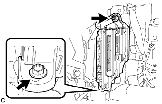
Remove the bolt, nut and ECU integration box RH.
-
-
REMOVE BRAKE PEDAL STROKE SENSOR ASSEMBLY
-
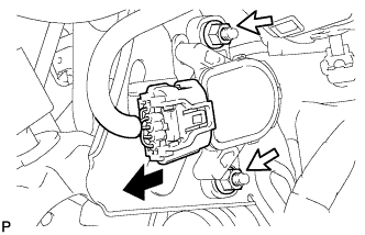
Disconnect the connector from the brake pedal stroke sensor assembly.
-
Remove the 2 nuts and brake pedal stroke sensor assembly.
Note
-
Do not drop the brake pedal stroke sensor assembly.
-
If the brake pedal stroke sensor assembly has been dropped, replace the brake pedal stroke sensor assembly with a new one.
-
-