TIRE PRESSURE WARNING SYSTEM Tire Pressure Warning Light Circuit
DESCRIPTION
If the tire pressure warning ECU and receiver detects any problems, the tire pressure warning light blinks for 1 minute then illuminates, and tire pressure monitoring is disabled at the same time. At this time, the ECU stores a DTC in memory.
Connecting terminals TC and CG of the DLC3 makes the tire pressure warning light blink to output DTCs.
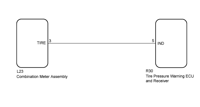
WIRING DIAGRAM
INSPECTION PROCEDURE
Note
-
When replacing the tire pressure warning ECU and receiver, read the transmitter IDs stored in the old ECU using the GTS and write them down before removal.
-
It is necessary to perform initialization Click here after registration Click here of the transmitter IDs into the tire pressure warning ECU and receiver if the ECU has been replaced.
PROCEDURE
-
CHECK OPERATION OF TIRE PRESSURE WARNING LIGHT (ACTIVE TEST)
-
Turn the power switch off.
-
Connect the GTS to the DLC3.
-
Turn the power switch on (IG).
-
Turn the GTS on.
-
Enter the following menus: Body Electrical / Combination Meter / Active Test.
-
Check the condition of the tire pressure warning light using the GTS.
Combination Meter Tester Display Test Part Control Range Diagnostic Note Indicat. Tire Pressure Warning System Tire pressure warning light OFF or ON - OK The tire pressure warning light turns on or off in accordance with the GTS operation.
NG 
GO TO METER / GAUGE SYSTEM Click here
OK 
-
-
CHECK HARNESS AND CONNECTOR (TIRE PRESSURE WARNING ECU AND RECEIVER - COMBINATION METER ASSEMBLY)
-
Disconnect the L23 combination meter assembly connector.
-
Disconnect the R30 tire pressure warning ECU and receiver connector.
-
Measure the resistance according to the value(s) in the table below.
Standard Resistance Tester Connection Condition Specified Condition R30-5 (IND) - L23-3 (TIRE) Always Below 1 Ω R30-5 (IND) or L23-3 (TIRE) - Body ground Always 10 kΩ or higher
NG
REPAIR OR REPLACE HARNESS OR CONNECTOR
OK 
REPLACE TIRE PRESSURE WARNING ECU AND RECEIVER Click here
-