TIRE PRESSURE WARNING SYSTEM TERMINALS OF ECU
-
CHECK TIRE PRESSURE WARNING ECU AND RECEIVER
-
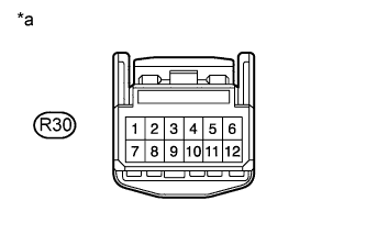
Text in Illustration *a Front view of wire harness connector
(to Tire Pressure Warning ECU and Receiver)
Disconnect the R30 tire pressure warning ECU and receiver connector and measure the voltage and resistance on the wire harness side.
Terminal No. (Symbol) Wiring Color Terminal Description Condition Specified Condition R30-1 (IG) - R30-12 (GND) B - W-B IG power source Power switch on (IG) 10 to 16 V R30-12 (GND) - Body ground W-B - Body ground Ground Always Below 1 Ω -
Connect the R30 tire pressure warning ECU and receiver connector.
-
Measure the voltage and resistance according to the value(s) in the table below. If the result is not as specified, the ECU may be malfunctioning.
Tech Tips
Inspect the connectors from the back side while the connectors are connected.

Text in Illustration *a Component with harness connected
(Tire Pressure Warning ECU and Receiver)
- - Terminal No. (Symbol) Wiring Color Terminal Description Condition Specified Condition R30-2 (SPD) - R30-12 (GND) V - W-B Vehicle speed signal Vehicle is running Pulse generation (see waveform 1) R30-3 (TC) - R30-12 (GND) L - W-B TC terminal Terminal TC is not connected 11 to 14 V R30-5 (IND) - R30-12 (GND) G - W-B Tire pressure warning light output signal
-
Power switch on (IG)
-
Tire pressure warning light off
3.2 V or higher
-
Power switch on (IG)
-
Tire pressure warning light on
0.9 to 3.2 V R30-7 (CLSW) - R30-12 (GND) Y - W-B Tire pressure warning reset switch signal
-
Power switch on (IG)
-
Tire pressure warning reset switch on
Below 1.5 V
-
Power switch on (IG)
-
Tire pressure warning reset switch off
8 to 15 V R30-10 (SIL) - R30-12 (GND) P - W-B Diagnostic tester communication line Power switch on (IG) 11 to 14 V -
-
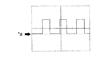
Text in Illustration *a GND Using an oscilloscope, check waveform 1.
Waveform 1: Item Contents Terminal R30-2 (SPD) - R30-12 (GND) Tool setting 5 V/DIV., 20 ms./DIV. Vehicle condition Driving at 20 km/h (12 mph) Tech Tips
The wavelength becomes shorter as the vehicle speed increases.
-