REAR WHEEL ALIGNMENT INSPECTION
Note
If a wheel alignment has been performed, or if suspension or underbody components have been removed/installed or replaced, be sure to perform the following initialization procedure in order for the system to function normally:
-
Perform zero point calibration of the yaw rate and acceleration sensor.
-
INSPECT TIRES
-
Check the tires for wear and proper inflation pressure.
Cold Tire Inflation Pressure Tire Size Front
kPa (kgf/cm2, psi)
Rear
kPa (kgf/cm2, psi)
195/65R15 91H 250 (2.5, 36) 240 (2.4, 35) -
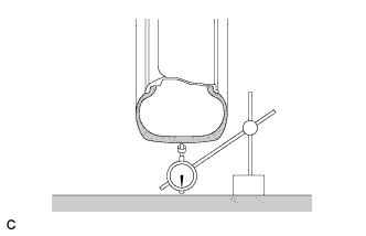
Using a dial indicator, check the runout of the tires.
Maximum tire runout 1.4 mm (0.0551 in.)
-
-
MEASURE VEHICLE HEIGHT
Note
-
Before inspecting the wheel alignment, adjust the vehicle height to the specified value.
-
Be sure to perform measurement on a level surface.
-
If it is necessary to go under the vehicle for measurement, confirm that the parking brake is applied and the vehicle is secured with chocks.
-
Inspect while the vehicle is unloaded.
-
The standard value shown here is a value that is used for performing a wheel alignment and does not indicate the height of an actual vehicle.
-
Bounce the vehicle up and down at the corners to stabilize the suspension.
-
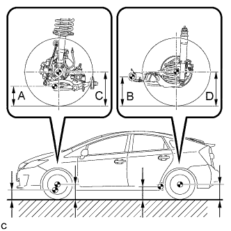
Measure the vehicle height.
-
A: Ground clearance of front lower No. 1 suspension arm bushing set bolt center
Measurement points:
-
B: Ground clearance of rear axle beam bushing set bolt center
-
C: Ground clearance of front wheel center
-
D: Ground clearance of rear wheel center
Vehicle Height (Unloaded Vehicle) Front C - A Rear D - B 106 mm (4.17 in.) 25 mm (0.984 in.) -
-
-
INSPECT CAMBER
Note
Inspect while the vehicle is unloaded.
-
Install a camber-caster-kingpin gauge.
-
Inspect the camber.
Camber (Unloaded Vehicle) Camber Inclination Right-left Difference -1°29' +/- 0°30' (-1.48° +/- 0.50°) 0°30' (0.50°) or less Tech Tips
Camber is not adjustable. If the measurement is not within the specified range, inspect the suspension parts for damage and/or wear, and replace them if necessary.
-
-
INSPECT TOE-IN
Note
Inspect while the vehicle is unloaded.
-
Bounce the vehicle up and down at the corners to stabilize the suspension.
-
Release the parking brake and move the shift lever to N.
-
Push the vehicle straight ahead approximately 5 m (16.4 ft.). (Step A)
-
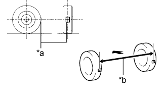
Text in Illustration *a Tread Center Mark *b Dimension B 
Front of the Vehicle Put tread center marks on the rearmost points of the rear wheels and measure the distance between the marks (dimension B).
-
Slowly push the vehicle straight ahead to cause the rear wheels to rotate 180°. Use the rear tire valve as a reference point.
Tech Tips
Do not allow the wheels to rotate more than 180°. If the wheels rotate more than 180°, perform the procedure from Step A again.
-
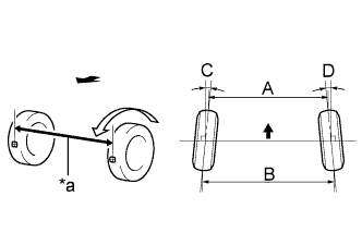
Text in Illustration *a Dimension A Front of the Vehicle Measure the distance between the tread center marks on the front of the wheels (dimension A).
Toe-in (Unloaded Vehicle) Specified Condition Right-left Difference C + D: 0°17' +/- 0°18' ( 0.28° +/- 0.30°) 0°45' (0.75°) or less B - A: 2.8 +/- 3.0 mm (0.110 +/- 0.118 in.) - Tech Tips
Measure "B - A" only when "C + D" cannot be measured.
If the toe-in is not within the specified range, inspect the suspension parts and replace them if necessary.
-