ELECTRONIC SHIFT LEVER SYSTEM, Diagnostic DTC:C2303
| DTC Code | DTC Name |
|---|---|
| C2303 | Short in Power Source Relay Circuit |
DESCRIPTION
The P-CON MTR relay (transaxle parking lock control relay) is activated by output voltage from the transmission control ECU assembly and supplies power to the shift control actuator assembly (parking lock motor). The transmission control ECU assembly stores this DTC when it detects a malfunction in the P-CON MTR relay (transaxle parking lock control relay).
| DTC No. | DTC Detection Condition | Trouble Area |
|---|---|---|
| C2303 | When the P-CON MTR relay (transaxle parking lock control relay) is off, voltage of transmission control ECU assembly terminal MUA, MVA and MWA are 6 V or more for 0.064 seconds or more. |
|
WIRING DIAGRAM
Refer to the wiring diagram for DTC C2301 Click here.
INSPECTION PROCEDURE
Note
It may not be possible to clear the following DTCs using the GTS: DTC C2300 (Actuator System Malfunction), C2301 (Shift Changing Time Malfunction), C2303 (Short in Power Source Relay Circuit), C2304 (Open or Short Circuit in U Phase), C2305 (Open or Short Circuit in V Phase), C2306 (Open or Short Circuit in W Phase), C2307 (Power Supply) and C2309 (Open in B+ Circuit). In such cases, disconnect the P CON MAIN fuse and wait for at least 60 seconds to clear the DTCs after the repair.
PROCEDURE
-
CHECK SHIFT CONTROL ACTUATOR ASSEMBLY (SHIFT CONTROL ACTUATOR ASSEMBLY POWER SOURCE CIRCUIT)
-
Disconnect the D2 shift control actuator assembly connector.
-
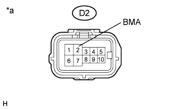
Text in Illustration *a Front view of wire harness connector
(to Shift Control Actuator Assembly)
Measure the voltage according to the value(s) in the table below.
Standard Voltage Tester Connection Condition Specified Condition D2-2 (BMA) - Body ground Power switch off Below 1 V -
Reconnect the D2 shift control actuator assembly connector.
NG 
INSPECT P-CON MTR RELAY (TRANSAXLE PARKING LOCK CONTROL RELAY) Click here
OK 
-
-
CHECK HARNESS AND CONNECTOR (TRANSMISSION CONTROL ECU ASSEMBLY - SHIFT CONTROL ACTUATOR ASSEMBLY)
-
Disconnect the A22 transmission control ECU assembly connector.
-
Disconnect the D2 shift control actuator assembly connector.
-
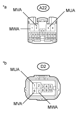
Text in Illustration *a Front view of wire harness connector
(to Transmission Control ECU Assembly)
*b Front view of wire harness connector
(to Shift Control Actuator Assembly)
Measure the resistance according to the value(s) in the table below.
Standard Resistance (Check for Short) Tester Connection Condition Specified Condition A22-5 (MUA) or D2-1 (MUA) - Body ground and other terminals Power switch off 10 kΩ or higher A22-2 (MVA) or D2-6 (MVA) - Body ground and other terminals Power switch off 10 kΩ or higher A22-1 (MWA) or D2-7 (MWA) - Body ground and other terminals Power switch off 10 kΩ or higher -
Reconnect the D2 shift control actuator assembly connector.
-
Reconnect the A22 transmission control ECU assembly connector.
NG 
REPAIR OR REPLACE HARNESS OR CONNECTOR
OK 
REPLACE TRANSMISSION CONTROL ECU ASSEMBLY Click here
-
-
INSPECT P-CON MTR RELAY (TRANSAXLE PARKING LOCK CONTROL RELAY)
-
Remove the P-CON MTR relay (transaxle parking lock control relay) from the engine room relay block and junction block assembly.
-
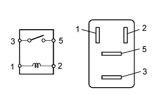
Measure the resistance according to the value(s) in the table below.
Standard Resistance Tester Connection Condition Specified Condition 3 - 5 Auxiliary battery voltage is not applied between terminals 1 and 2 10 kΩ or higher Auxiliary battery voltage is applied between terminals 1 and 2 Below 1 Ω -
Reinstall the P-CON MTR relay (transaxle parking lock control relay).
NG
REPLACE P-CON MTR RELAY (TRANSAXLE PARKING LOCK CONTROL RELAY)
OK
-
-
CHECK HARNESS AND CONNECTOR (TRANSMISSION CONTROL ECU ASSEMBLY - P-CON MTR RELAY)
-
Disconnect the A22 transmission control ECU assembly connector.
-
Remove the P-CON MTR relay (transaxle parking lock control relay) from the engine room relay block and junction block assembly.
-
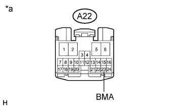
Text in Illustration *a Front view of wire harness connector
(to Transmission Control ECU Assembly)
Measure the resistance according to the value(s) in the table below.
Standard Resistance (Check for Short) Tester Connection Condition Specified Condition A22-23 (BMA) - Body ground and other terminals Power switch off 10 kΩ or higher -
Reinstall the P-CON MTR relay (transaxle parking lock control relay).
-
Reconnect the A22 transmission control ECU assembly connector.
NG
REPAIR OR REPLACE HARNESS OR CONNECTOR
OK
-
-
CHECK HARNESS AND CONNECTOR (SHIFT CONTROL ACTUATOR ASSEMBLY - P-CON MTR RELAY)
-
Disconnect the D2 shift control actuator assembly connector.
-
Remove the P-CON MTR relay (transaxle parking lock control relay) from the engine room relay block and junction block assembly.
-

Text in Illustration *a Front view of wire harness connector
(to Shift Control Actuator Assembly)
Measure the resistance according to the value(s) in the table below.
Standard Resistance (Check for Short) Tester Connection Condition Specified Condition D2-2 (BMA) - Body ground and other terminals Power switch off 10 kΩ or higher -
Reinstall the P-CON MTR relay (transaxle parking lock control relay).
-
Reconnect the D2 shift control actuator assembly connector.
NG
REPAIR OR REPLACE HARNESS OR CONNECTOR
OK
CHECK FOR INTERMITTENT PROBLEMS Click here
-