MILLIMETER WAVE RADAR SENSOR INSTALLATION

-
INSTALL MILLIMETER WAVE RADAR SENSOR ASSEMBLY
-
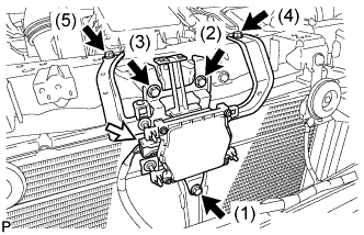
Tighten the 5 bolts on the millimeter wave radar sensor assembly.
- Torque:
- 6.2 N*m { 63 kgf*cm, 55 in.*lbf }
Tech Tips
Tighten the bolts in the order indicated in the illustration.
-
Connect the connector.
-
-
INSTALL FRONT BUMPER ASSEMBLY
-
w/ Headlight Cleaner System:
-
Connect the headlight cleaner hose.
-
-
Connect the connector.
-
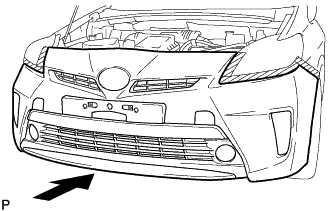
Install the front bumper assembly as shown in the illustration.
-
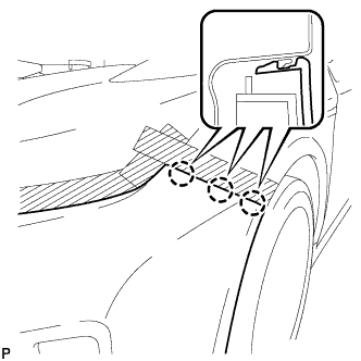
Engage the 3 claws to install the front bumper assembly.
Tech Tips
Use the same procedure for the RH side and LH side.
-
Engage the 2 guides to install the front spoiler cover.
-
Install the 2 clips and 4 screws.
-
Install the 7 clips.
-
Install the 2 bolts and 2 screws.
-
Install the screw.
Tech Tips
Use the same procedure for the RH side and LH side.
-
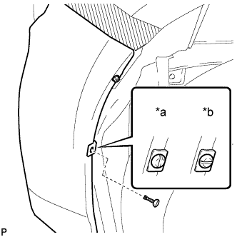
Text in Illustration *a Correct *b Incorrect Install the pin hold clip.
Note
Insert the pin hold clip with the slot aligned vertically. Do not rotate the clip after inserting it. After installation, confirm that the slot is vertical.
Tech Tips
Use the same procedure for the RH side and LH side.
-
-
ADD WASHER FLUID
-
Add washer fluid to the washer jar.
-
-
ADJUST FOG LIGHT AIMING
-
ADJUST MILLIMETER WAVE RADAR SENSOR ASSEMBLY
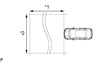
Text in Illustration *1 Approx. 10 m *2 Approx. 14 m Note
-
Perform measurements on a level surface.
-
Make sure that no large pieces of metal are within a 10 m (32.8 ft.) x 14 m (45.9 ft.) area in front of the vehicle. If possible, the surrounding area should also be free of large metal objects.
-
Before adjusting the radar beam axis, prepare the vehicle as follows.
-
Remove all excess weight from the vehicle (luggage, heavy objects, etc.).
-
Check the tire pressure and adjust it if necessary Click here.
-
-
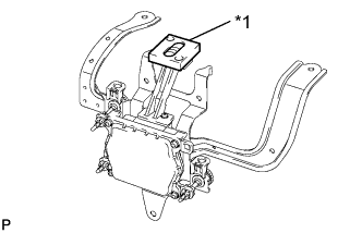
Text in Illustration *1 Level Check and adjust the vertical direction of the radar sensor.
-
Remove dust, oil and foreign matter from the radar sensor's level rack.
-
Set a level on the radar sensor's level rack.
-
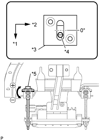
Text in Illustration *1 FR *2 LH *3 Level *4 Air Bubble *5 Bolt A Check that the level's air bubble is within the red frame.
OK Level's air bubble is within the red frame. If the bubble is not within the red frame, use a screwdriver to adjust the bolt A until the air bubble is within the red frame.
Tech Tips
-
The adjustable range within the level's red frame is +/-0.2°.
-
The target angle is +0.2° (upward angle of 0.2°).
Result Adjustment Direction Adjustment Procedure Adjustment Angle Vertical adjustment Upward direction: Turn screwdriver to negative (-) side When screwdriver is turned once, adjustment changes by about 0.12°. Downward direction: Turn screwdriver to positive (+) side
-
-
-
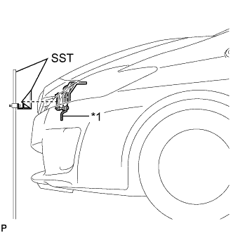
Text in Illustration *1 Millimeter Wave Radar Sensor Adjust the reflector height.
-
Adjust the reflector so that the center of SST reflector is the same height as the millimeter wave radar sensor.
- SST
- 09870-60000 ( 09870-60010 )
- 09870-60040
Tech Tips
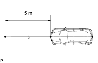
Prepare a 10 m (32.8 ft.) string, string with a sharp-pointed weight (plumb bob), and 5 m (16.4 ft.) tape measure.
-
-
Place the reflector.
-
Hang the string (with weight) from the center of the vehicle's rear emblem. Mark the vehicle's rear center point on the ground. Repeat for the front of the vehicle.
-
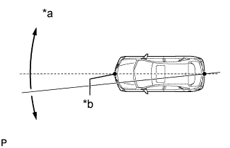
Text in Illustration *a Adjust center by moving string to right and left *b Extend string through front center mark Set one end of the 10 m (32.8 ft.) string on the vehicle's rear center point. Run the string over the vehicle's front center point to a position 5 m (16.4 ft.) beyond the vehicle's front center point, as shown in the illustration. Mark the 5 m (16.4 ft.) position.
-
Using a tape measure, measure 15.7 mm (0.618 in.) to the right of the 5 m (16.4 ft.) position. Place the reflector at that position.
Note
Perform the operation as precisely as possible.
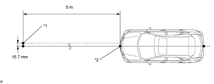
Text in Illustration *1 Reflector Placement Point *2 Millimeter Wave Radar Sensor Position
-
-
Check the radar beam axis.
-
When using the GTS:
-
Connect the GTS to the DLC3.
-
Turn the power switch on (IG).
-
Turn the GTS on, and turn the cruise control main switch on.
-
Select "Connect to Vehicle".
-
Select each item on the display screen and proceed to the next screen.
-
Under "System Selection Menu", select "Radar Cruise".
-
Select "Utility".
-
Select "Beam Axis Adjustment" and proceed to the next screen.
Tech Tips
A buzzer will sound for 1 second.
-
Follow the GTS display, and continue with the adjustment.
CAUTION:
Do not come within 20 cm (7.87 in.) of the radar sensor.
Note
-
Turn the cruise control main switch on before pressing "Next".
-
Make sure there is at least 20 cm (7.87 in.) between the radar sensor and any nearby individuals.
-
-
-
Check the following items on the laser cruise divergence data screen.
Note
While using the GTS beam axis adjustment mode, the actual direction and angle of the radar sensor may be different from the GTS data. In such a case, the deviation is displayed on the combination meter's multi-information display.
-
Confirm that the distance value is approximately 5 m (16.4 ft.).
Tech Tips
-
A value between 0.0 m (0.0 ft.) and 6.3 m (20.7 ft.) should be indicated.
-
If the distance is 0.0 m (0.0 ft.), the sensor cannot detect the target. Reconfirm that there is no metal in the specified area in front of the vehicle (refer to the Notice at the beginning of this adjustment procedure).
-
-
Confirm that the left/right side value is between 0.0 m (0.0 ft.) and 6.3 m (20.7 ft.).
Tech Tips
If the distance is 0.0 m (0.0 ft.), the sensor cannot detect the target. Reconfirm that there is no metal in the specified area in front of the vehicle (refer to the Notice at the beginning of this adjustment procedure).
-
-
-
Check and adjust the horizontal direction of the radar sensor.
-
Check that the divergence of the radar beam axis is 0°.
Standard 0° (Both right and left) If the axis is not as specified, use a screwdriver to adjust the bolt B until the divergence of the radar beam axis is 0°.
-
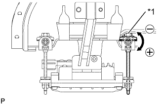
Text in Illustration *1 Bolt B Based on the measured divergence of the beam axis, turn and adjust the bolt B for horizontal adjustment of the millimeter wave radar sensor using a screwdriver.
Result Adjustment Direction Adjustment Procedure Adjustment Angle Horizontal adjustment Right direction: Turn screwdriver to positive (+) side. When screwdriver is turned once, adjustment changes by about 0.07°. Left direction: Turn screwdriver to negative (-) side. Tech Tips
-
If "LEFT SIDE: 1.0°" is displayed, the divergence is 1.0° in the left direction. Turn the bolt B approximately 2.5 turns to the negative (-) side.
-
If the value does not change to 0°, it is possible that the sensor is aiming at something different. Reconfirm that there are no reflective materials in the surrounding area.
-
-
Select "Next". The driving learning value is automatically reset.
Tech Tips
A buzzer will sound for 10 seconds or more.
-
Disconnect the GTS from the DLC3.
-
-
Recheck and readjust the vertical direction of the radar sensor.
-
Text in Illustration *1 Level Set a level on the radar sensor's level rack.
-
Text in Illustration *1 FR *2 LH *3 Level *4 Air Bubble *5 Bolt A Check that the level's air bubble is within the red frame.
OK Level's air bubble is within the red frame. If the bubble is not within the red frame, use a screwdriver to adjust the bolt A until the level's air bubble is within the red frame.
Tech Tips
-
The adjustable range within the red frame is +/-0.2°.
-
The target angle is +0.2° (upward angle of 0.2°).
Result Adjustment Direction Adjustment Procedure Adjustment Angle Vertical adjustment Upward direction: Turn screwdriver to negative (-) side When screwdriver is turned once, adjustment changes by about 0.12°. Downward direction: Turn screwdriver to positive (+) side
-
-
-
-
INSTALL RADIATOR SUPPORT OPENING COVER
-
Engage the 2 claws to install the radiator support opening cover.
-
Install the 3 clips.
-