DRIVING SUPPORT ECU INSTALLATION
-
INSTALL DRIVING SUPPORT ECU ASSEMBLY (for LHD)
-
Engage the claw to install the driving support ECU assembly.
Tech Tips
If the park assist ECU was removed, install it after installing the driving support ECU assembly Click here.
-
-
INSTALL DRIVING SUPPORT ECU ASSEMBLY (for RHD)
-
Engage the claw to install the driving support ECU assembly.
Tech Tips
If the park assist ECU was removed, install it after installing the driving support ECU assembly Click here.
-
-
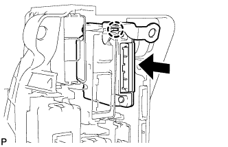
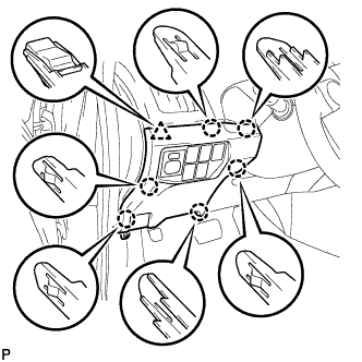
INSTALL ECU INTEGRATION BOX RH
-
for LHD:
-
Install the ECU integration box RH with the 2 nuts and bolt.
- Torque:
- Nut
- 5.5 N*m { 56 kgf*cm, 49 in.*lbf }
- Bolt
- 8.0 N*m { 82 kgf*cm, 71 in.*lbf }
-
Engage the 3 clamps to connect the wire harness.
-
Connect each connector.
-
-
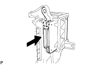
for RHD:
-
Install the ECU integration box RH with the nut and bolt.
- Torque:
- Nut
- 5.5 N*m { 56 kgf*cm, 49 in.*lbf }
- Bolt
- 13 N*m { 127 kgf*cm, 9 ft.*lbf }
-
Engage the clamp to connect the wire harness.
-
Connect each connector.
-
-
-
INSTALL GLOVE COMPARTMENT DOOR ASSEMBLY (for LHD)
-
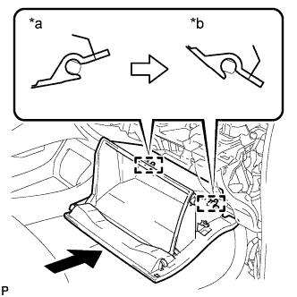
Text in Illustration *a Opened Approximately 55° *b Closed With the glove compartment door assembly opened approximately 55° from its closed position, engage the 2 hinges horizontally.
Note
Engaging the hinges from the top will deform the hinges. Be sure to install the glove compartment door assembly horizontally.
-
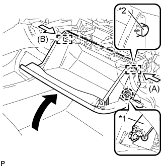
Text in Illustration *1 Glove Compartment Door Stopper Sub-assembly *2 Stopper Slightly bend the stoppers (A) and (B) in the directions indicated by the arrows in the illustration and engage the stoppers to install the glove compartment door assembly.
-
Engage the claw and connect the glove compartment door stopper sub-assembly.
-
-
INSTALL NO. 2 INSTRUMENT PANEL UNDER COVER SUB-ASSEMBLY (for LHD)
-
Connect each connector.
-
Engage the guide and 3 claws to install the No. 2 instrument panel under cover sub-assembly.
-
-
INSTALL LOWER INSTRUMENT PANEL FINISH PANEL ASSEMBLY (for RHD)
-
Connect each connector.
-
Engage the clamp.
-
Engage the 2 guides and claw to connect the hood lock control cable.
-
Engage the 6 claws and clip.
-
Install the lower instrument panel finish panel assembly with the screw <C>.
-
-
INSTALL COWL SIDE TRIM BOARD RH (for RHD)
Tech Tips
Use the same procedure as for the LH side Click here.
-
INSTALL FRONT DOOR SCUFF PLATE RH (for RHD)
Tech Tips
Use the same procedure as for the LH side Click here.
-
CONNECT CABLE TO NEGATIVE AUXILIARY BATTERY TERMINAL
Note
When disconnecting the cable, some systems need to be initialized after the cable is reconnected Click here.
-
INSTALL REAR NO. 3 FLOOR BOARD UPPER PLATE
-
Engage the 2 claws to install the rear No. 3 floor board upper plate.
-
-
INSTALL DECK FLOOR BOX RH
-
Install the deck floor box RH Click here.
-
Install the rear No. 2 floor board.
-
-
INSTALL REAR NO. 3 FLOOR BOARD
-
Install the rear No. 3 floor board.
-