DYNAMIC RADAR CRUISE CONTROL SYSTEM Cruise Main Indicator Light Circuit
DESCRIPTION
When the cruise control system is turned on using the cruise control switch (ON-OFF button), the cruise control indicator light (vehicle-to-vehicle distance control mode) illuminates. The driving support ECU uses these and other indicators to indicate the control condition (presence or absence of a vehicle in front, vehicle-to-vehicle distance, and set vehicle speed) and fail-safe state through the CAN communication system.
Tech Tips
If the preceding vehicle in the same lane significantly decreases vehicle speed or another vehicle moves in front of your vehicle, adequate deceleration cannot be applied by the cruise control system and the vehicle-to-vehicle distance will become shorter. At this time, the system sounds the buzzer to warn the driver. The indicators for the dynamic radar cruise control system use CAN for communication. Therefore, if there are any indicator malfunctions, check for DTCs in the CAN communication system before troubleshooting this circuit.
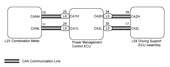
WIRING DIAGRAM
INSPECTION PROCEDURE
PROCEDURE
-
PERFORM ACTIVE TEST USING GTS
-
Connect the GTS to the DLC3.
-
Turn the power switch on (IG).
-
Turn the GTS on.
-
Enter the following menus: Body Electrical / Combination Meter / Active Test.
-
Check the cruise control indicator light by performing Active Test.
Combination Meter Tester Display Test Part Control Range Diagnostic Note Indicat. Lamp Cruise Cruise control indicator light
(Constant speed control mode)
Cruise control indicator light (Constant speed control mode) OFF or ON - Indicat. Radar Cruise Cruise control indicator light
(Vehicle-to-vehicle distance control mode)
Cruise control indicator light (Vehicle-to-vehicle distance control mode) OFF or ON - OK The display changes in accordance with Active Test operation.
NG 
REPLACE METER CIRCUIT PLATE NO. 3 Click here
OK 
REPLACE PROCEED TO NEXT SUSPECTED AREA SHOWN IN PROBLEM SYMPTOMS TABLE Click here
-