ROOF HEADLINING REMOVAL

-
PRECAUTION
Note
After turning the ignition switch off, waiting time may be required before disconnecting the cable from the battery terminal. Therefore, make sure to read the disconnecting the cable from the battery terminal notice before proceeding with work Click here.
-
DISCONNECT CABLE FROM NEGATIVE BATTERY TERMINAL
CAUTION:
Wait at least 90 seconds after disconnecting the cable from the negative (-) battery terminal to disable the SRS system.
Note
When disconnecting the cable, some systems need to be initialized after the cable is reconnected Click here.
-
REMOVE REAR NO. 2 SEAT ASSEMBLY RH
-
REMOVE REAR NO. 2 SEAT ASSEMBLY LH
Tech Tips
Use the same procedure described for the RH side.
-
REMOVE FRONT DOOR SCUFF PLATE LH
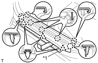
Text in Illustration *1 Protective Tape
-
Put protective tape around the front door scuff plate.
-
Using a moulding remover, detach the 7 claws and 3 clips and remove the front door scuff plate.
-
-
REMOVE FRONT DOOR SCUFF PLATE RH
Tech Tips
Use the same procedure described for the LH side.
-
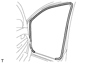
REMOVE FRONT DOOR OPENING TRIM LH
-
Remove the front door opening trim.
-
-
REMOVE FRONT DOOR OPENING TRIM RH
Tech Tips
Use the same procedure described for the LH side.
-
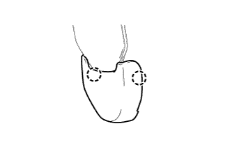
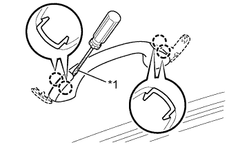
REMOVE FRONT NO. 1 ASSIST GRIP PLUG LH
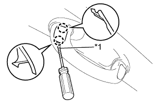
Text in Illustration *1 Protective Tape Tech Tips
Use the same procedure for both front No. 1 assist grip plugs.
-
Using a screwdriver, detach the 2 claws and remove the front No. 1 assist grip plug.
Tech Tips
Tape the screwdriver tip before use.
-
-
REMOVE FRONT NO. 1 ASSIST GRIP PLUG RH
Tech Tips
Use the same procedure described for the LH side.
-
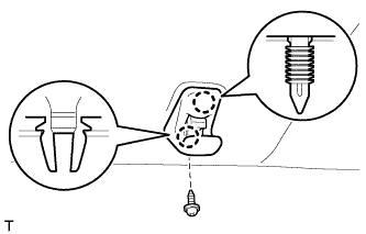
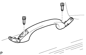
REMOVE FRONT ASSIST GRIP SUB-ASSEMBLY
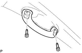
Tech Tips
Use the same procedure for both front assist grips.
-
Remove the 2 screws and front assist grip.
-
-
REMOVE FRONT PILLAR GARNISH LH
-
Detach the 2 clips and 2 guides and remove the front pillar garnish.
-
-
REMOVE FRONT PILLAR GARNISH RH
Tech Tips
Use the same procedure described for the LH side.
-
REMOVE REAR DOOR SCUFF PLATE LH
Text in Illustration *1 Protective Tape
-
Put protective tape around the rear door scuff plate.
-
Using a moulding remover, detach the 7 claws and 2 clips and remove the rear door scuff plate.
-
-
REMOVE REAR DOOR SCUFF PLATE RH
Tech Tips
Use the same procedure described for the LH side.
-
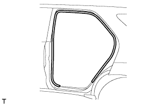
REMOVE REAR DOOR OPENING TRIM WEATHERSTRIP LH
-
Remove the rear door opening trim weatherstrip.
-
-
REMOVE REAR DOOR OPENING TRIM WEATHERSTRIP RH
Tech Tips
Use the same procedure described for the LH side.
-
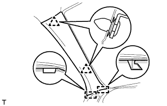
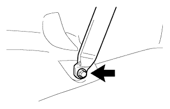
REMOVE LOWER CENTER PILLAR GARNISH LH
-
Detach the 2 claws and remove the outer lap belt anchor cover.
-
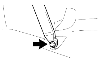
Remove the bolt and disconnect the front seat outer belt floor anchor.
-
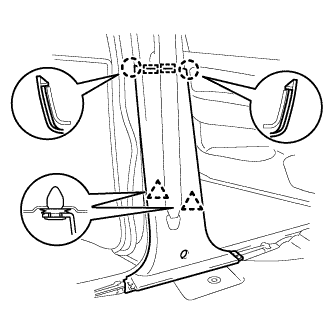
Detach the 2 claws, 2 guides and 2 clips and remove the lower center pillar garnish.
-
-
REMOVE LOWER CENTER PILLAR GARNISH RH
Tech Tips
Use the same procedure described for the LH side.
-
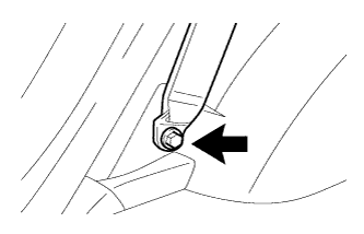
REMOVE CENTER PILLAR GARNISH LH
-
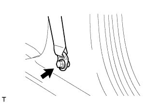
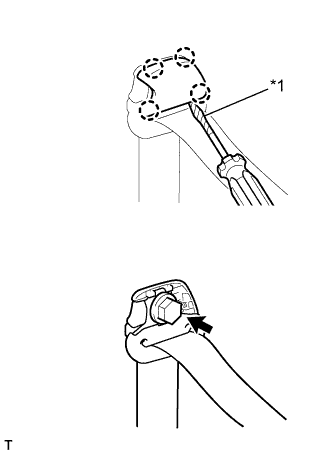
Using a screwdriver, detach the 4 claws and remove the front seat belt shoulder anchor cover.
Tech Tips
Tape the screwdriver tip before use.
Text in Illustration *1 Protective Tape -
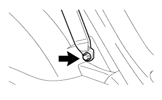
Remove the bolt and disconnect the front seat belt shoulder anchor.
-
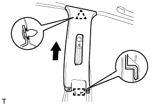
Detach the clip.
-
Pull the center pillar garnish in the direction indicated by the arrow in the illustration to detach the guide and remove the center pillar garnish.
-
-
REMOVE CENTER PILLAR GARNISH RH
Tech Tips
Use the same procedure described for the LH side.
-
REMOVE BACK DOOR SCUFF PLATE
-
Detach the 4 claws, 2 guides and 6 clips and remove the back door scuff plate.
-
-
REMOVE QUARTER TRIM HOOK
Tech Tips
Use the same procedure for both quarter trim hooks.
-
Remove the screw and quarter trim hook.
-
-
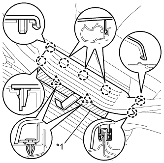
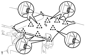
REMOVE QUARTER INSIDE TRIM BOARD LH
-
Detach the 2 claws and remove the outer lap belt anchor cover.
Tech Tips
Use the same procedure for both outer lap belt anchor covers.
-
Remove the bolt and disconnect the rear No. 1 seat outer belt floor anchor.
-
Remove the bolt and disconnect the rear No. 2 seat outer belt floor anchor.
-
Using a clip remover, remove the clip.
-
Detach the 7 claws and 10 clips.
-
Disconnect the power point socket connector and remove the quarter inside trim board.
-
-
REMOVE QUARTER INSIDE TRIM BOARD RH
-
Detach the 2 claws and remove the outer lap belt anchor cover.
Tech Tips
Use the same procedure for both outer lap belt anchor covers.
-
Remove the bolt and disconnect the rear No. 1 seat outer belt floor anchor.
-
Remove the bolt and disconnect the rear No. 2 seat outer belt floor anchor.
-
Using a clip remover, remove the clip.
-
Detach the 8 claws and 10 clips and remove the quarter inside trim board.
-
-
REMOVE QUARTER PILLAR GARNISH LH
-
Using a screwdriver, detach the 2 claws and open the rear No. 1 seat belt shoulder anchor cover.
Tech Tips
Tape the screwdriver tip before use.
Text in Illustration *1 Protective Tape -
Remove the bolt and disconnect the rear No. 1 seat belt shoulder anchor.
-
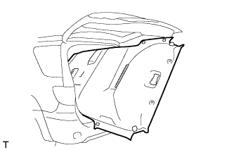
Detach the 9 clips and remove the quarter pillar garnish.
-
-
REMOVE QUARTER PILLAR GARNISH RH
Tech Tips
Use the same procedure described for the LH side.
-
REMOVE INNER UPPER ROOF SIDE GARNISH LH
-
Using a screwdriver, detach the 2 claws and open the rear No. 2 seat belt shoulder anchor cover.
Tech Tips
Tape the screwdriver tip before use.
Text in Illustration *1 Protective Tape -
Remove the bolt and disconnect the rear No. 2 seat belt shoulder anchor.
-
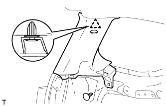
Using a clip remover, remove the clip.
-
Detach the clip and remove the inner upper roof side garnish.
-
-
REMOVE INNER UPPER ROOF SIDE GARNISH RH
Tech Tips
Use the same procedure described for the LH side.
-
REMOVE MAP LIGHT ASSEMBLY
-
Remove the 2 screws.
-
Detach the claw and 2 guides and remove the map light assembly.
-
Disconnect the connector.
-
-
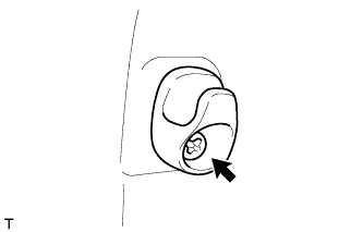
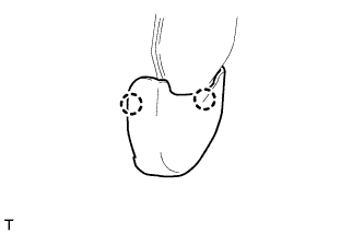
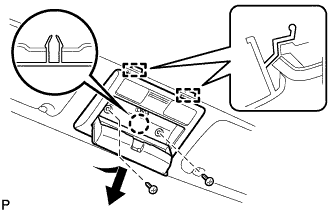
REMOVE COOLER CONTROL SWITCH ASSEMBLY
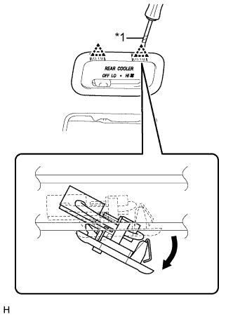
Text in Illustration *1 Protective Tape
-
Using a screwdriver, detach the 2 clips and remove the cooler control switch assembly (rear blower control switch) as shown in the illustration.
Tech Tips
Tape the screwdriver tip before use.
-
-
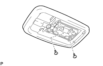
REMOVE NO. 1 ROOM LIGHT ASSEMBLY
-
Remove the 2 screws and room light.
-
Disconnect the light connector.
-
-
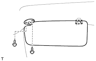
REMOVE VISOR ASSEMBLY LH
-
Detach the guide.
-
Remove the 2 screws and visor.
-
-
REMOVE VISOR ASSEMBLY RH
Tech Tips
Use the same procedure described for the LH side.
-
REMOVE VISOR HOLDER LH
-
Remove the screw.
-
Detach the 2 claws and remove the visor holder.
-
-
REMOVE VISOR HOLDER RH
Tech Tips
Use the same procedure described for the LH side.
-
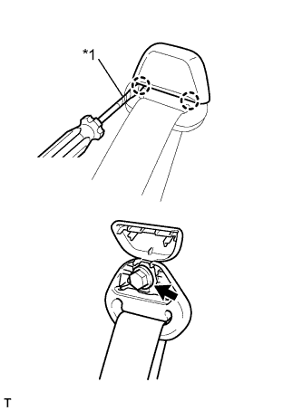
REMOVE ASSIST GRIP
Tech Tips
Use the same procedure for all assist grips.
-
Using a screwdriver, detach the 4 claws and open the 2 covers.
Tech Tips
Tape the screwdriver tip before use.
Text in Illustration *1 Protective Tape -
Remove the 2 screws and assist grip.
-
-
REMOVE UPPER INSTRUMENT PANEL SUB-ASSEMBLY
-
REMOVE LOWER INSTRUMENT PANEL FINISH PANEL SUB-ASSEMBLY
-
Detach the 2 claws, 3 clips and 3 guides and remove the lower instrument panel finish panel.
-
-
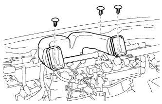
REMOVE NO. 2 HEATER TO REGISTER DUCT
-
Remove the 3 clips and No. 2 heater to register duct.
-
-
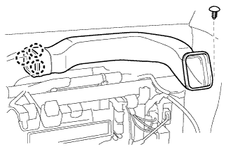
REMOVE NO. 1 HEATER TO REGISTER DUCT
-
Remove the clip.
-
Detach the 3 claws and remove the No. 1 heater to register duct.
-
-
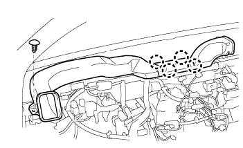
REMOVE NO. 3 HEATER TO REGISTER DUCT
-
Remove the clip.
-
Detach the 4 claws and remove the No. 3 heater to register duct.
-
-
REMOVE DEFROSTER NOZZLE ASSEMBLY
-
Using a screwdriver, detach the 4 clips and remove the defroster nozzle assembly.
-
-
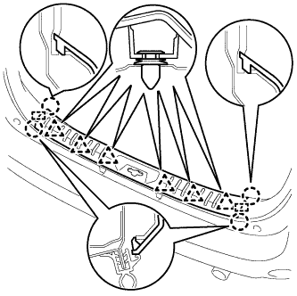
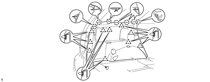
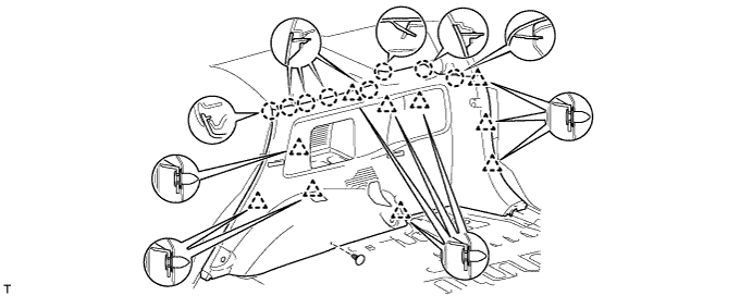
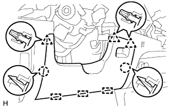
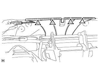
REMOVE ROOF HEADLINING ASSEMBLY
-
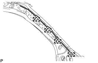
Detach the 4 clamps from the front pillar.
-
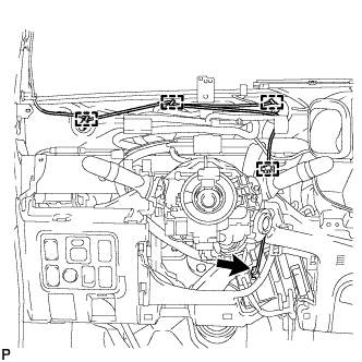
Disconnect the connectors and detach the 4 clamps.
-
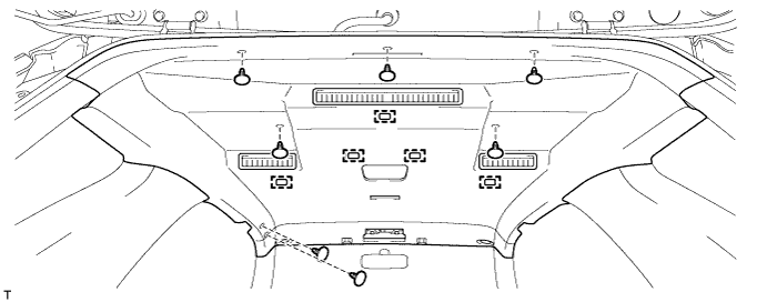
Using a clip remover, remove the 7 clips.
-
Detach the 5 fasteners.
-
Remove the roof headlining as shown in the illustration.
Note
Be careful not to damage the roof headlining when removing it.
-
-
REMOVE FRONT SIDE RAIL SPACER LH
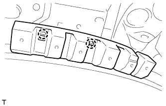
-
Detach the 2 claws and remove the front side rail spacer.
-
-
REMOVE FRONT SIDE RAIL SPACER RH
Tech Tips
Use the same procedure described for the LH side.
-
REMOVE SIDE RAIL SPACER
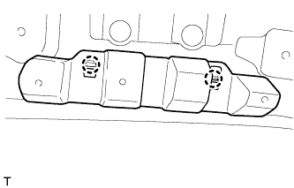
-
Detach the 2 claws and remove the side rail spacer.
-
-
REMOVE REAR NO. 2 SIDE RAIL SPACER LH
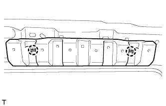
Tech Tips
Use the same procedure for all No. 2 side rail spacers.
-
Detach the 2 claws and remove the rear No. 2 side rail spacer.
-
-
REMOVE REAR NO. 2 SIDE RAIL SPACER RH
Tech Tips
Use the same procedure described for the LH side.
-
REMOVE REAR NO. 3 SIDE RAIL SPACER LH
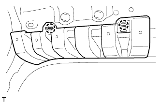
-
Detach the 3 claws and remove the rear No. 3 side rail spacer.
-
-
REMOVE REAR NO. 3 SIDE RAIL SPACER RH
Tech Tips
Use the same procedure described for the LH side.