BACK DOOR REASSEMBLY

Tech Tips
A bolt without a torque specification is shown in the standard bolt chart Click here.
-
INSTALL BACK DOOR STAY ASSEMBLY LH
-
When using a new bolt:
-
Clean the threaded portion on the vehicle body with a non-residue solvent.
-
-
When reusing a bolt:
-
Clean the threaded portion on the vehicle body and bolt with a non-residue solvent.
-
Apply adhesive to the threads of the bolt.
Adhesive Toyota Genuine Adhesive 1324, Three Bond 1324 or equivalent
-
-
Install the back door stay with the 4 bolts.
- Torque:
- 7.5 N*m { 76 kgf*cm, 66 in.*lbf }
CAUTION:
Install the back door stay while holding the back door.
-
-
INSTALL BACK DOOR STAY ASSEMBLY RH
Tech Tips
Use the same procedure described for the LH side.
-
INSTALL BACK DOOR LOWER STOPPER
Tech Tips
Use the same procedure for both back door lower stoppers.
-
Install the back door lower stopper with the bolt.
- Torque:
- 7.0 N*m { 71 kgf*cm, 62 in.*lbf }
-
-
INSTALL BACK DOOR PANEL CUSHION
Tech Tips
Use the same procedure for both back door panel cushions.
-
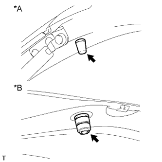
Text in Illustration *1 for Upper Side *2 for Lower Side Install 2 new back door panel cushions.
-
-
INSTALL BACK DOOR GLASS CHANNEL LH
Tech Tips
When installing the back door glass channel LH, heat the vehicle body using a heat light.
Standard Item Temperature Vehicle Body 40 to 60°C (104 to 140°F) Note
Do not heat the vehicle body excessively.
-
Clean the vehicle body surface.
-
Using a heat light, heat the vehicle body surface.
-
Remove the double-sided tape from the vehicle body.
-
Wipe off any tape adhesive residue with cleaner.
-
-
Install a new back door glass channel.
-
Using a heat light, heat the vehicle body.
-
Remove the peeling paper from the face of a new back door glass channel.
Tech Tips
After removing the peeling paper, keep the exposed adhesive free from foreign matter.
-
Install the back door glass channel.
Tech Tips
Press the back door glass channel firmly to install it.
-
Install the 2 clips.
-
-
-
INSTALL BACK DOOR GLASS CHANNEL RH
Tech Tips
Use the same procedure described for the LH side.
-
INSTALL REAR WASHER NOZZLE SUB-ASSEMBLY
-
Attach the 2 claws to install the rear washer nozzle.
-
Connect the hose.
-
-
INSTALL REAR SPOILER
-
Attach the 4 clips to install the rear spoiler.
-
Install the 3 nuts.
- Torque:
- 7.8 N*m { 80 kgf*cm, 69 in.*lbf }
-
Install the 2 grommets.
-
-
INSTALL NO. 2 BACK DOOR SERVICE HOLE COVER
-
Connect the connector and attach the clamp.
-
Attach the 4 claws to install the No. 2 back door service hole cover.
-
-
INSTALL REAR WIPER MOTOR GROMMET
-
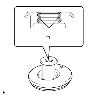
Text in Illustration *1 MP grease Apply MP grease to the entire inner surface of the wiper motor grommet.
Tech Tips
Make sure that grease is applied so that the grooves in the grommet are filled with grease, but not so that the hole of the grommet becomes clogged with grease.
-
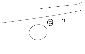
Text in Illustration *1 Position Mark Install the rear wiper motor grommet with the position mark facing upward as shown in the illustration.
-
-
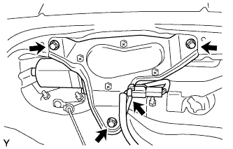
INSTALL REAR WIPER MOTOR ASSEMBLY
-
Install the wiper motor with the 3 bolts.
- Torque:
- 8.3 N*m { 85 kgf*cm, 73 in.*lbf }
-
Connect the connector.
-
-
INSTALL REAR WIPER ARM AND BLADE ASSEMBLY
-
Operate the rear wiper, and stop the rear wiper motor at the automatic stop position.
-
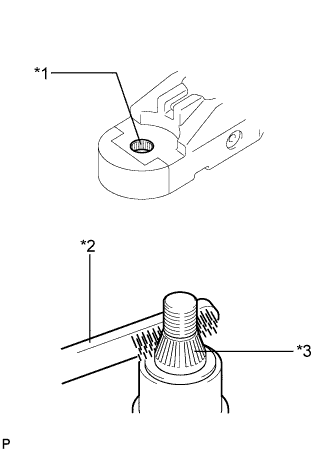
Text in Illustration *1 Wiper Arm Pivot Serrations *2 Wire Brush *3 Wiper Pivot Serrations Clean the wiper pivot serrations with a wire brush.
-
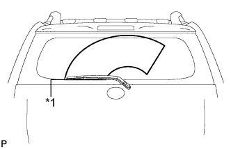
Text in Illustration *1 Ceramic Line Install the arm and blade with the nut. Make sure that the arm and blade comes to the position shown in the illustration.
- Torque:
- 8.4 N*m { 86 kgf*cm, 74 in.*lbf }
Tech Tips
-
Hold down the arm hinge by hand while tightening the nut.
-
Install the arm and blade so that the rear wiper blade is aligned with the ceramic line.
-
Operate the rear wiper while spraying water or washer fluid on the glass. Make sure that there is no interference between the blade and pillar.
-
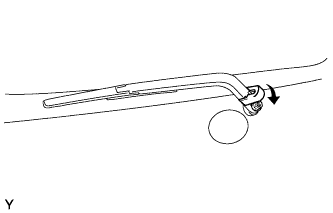
Close the wiper arm head cap.
-
-
INSTALL REAR LIGHT ASSEMBLY LH
-
Connect the connector.
-
Attach the rear combination light assembly LH with the clip and pin.
-
Install the 2 bolts to install the rear combination light assembly LH.
-
-
INSTALL REAR LIGHT ASSEMBLY RH
Tech Tips
Use the same procedure described for the LH side.
-
INSTALL BACK DOOR OUTSIDE GARNISH
-
Attach the 2 clips to install the back door outside garnish.
-
w/ Rear View Monitor System:
Install the nut.
-
w/o Rear View Monitor System:
Install the 3 nuts.
-
-
INSTALL REAR TELEVISION CAMERA ASSEMBLY (w/ Rear View Monitor System)
-
Install the rear television camera assembly with the 2 nuts.
-
Connect the connector.
-
-
INSTALL BACK DOOR OUTSIDE HANDLE
-
Install the back door outside handle with the 2 nuts.
-
-
INSTALL BACK DOOR LOCK ASSEMBLY
-
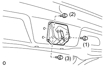
Temporarily install the back door lock assembly with the 3 bolts.
-
Tighten the bolts in the order shown in the illustration.
- Torque:
- 15 N*m { 153 kgf*cm, 11 ft.*lbf }
-
Attach the back door lock cable assembly.
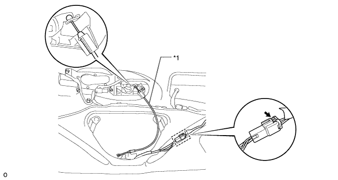
Text in Illustration *1 Back Door Lock Cable Assembly - - -
Connect the clamp and connect the connector.
-
-
INSTALL BACK DOOR TRIM BOARD ASSEMBLY
-
Attach the 16 clips to install the back door trim board.
-
-
INSTALL DOOR PULL HANDLE
-
Attach the 4 clips to install the door pull handle.
-