FRONT POWER SEAT MOTOR ASSEMBLY (for Rear Lifter) REMOVAL

-
REMOVE FRONT SEAT ASSEMBLY
-
Remove the front seat assembly Click here.
-
-
REMOVE RECLINING POWER SEAT SWITCH KNOB
-
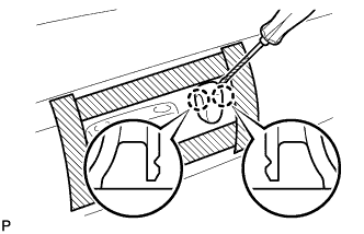
Apply protective tape around the cushion shield.
-
Using a screwdriver, detach the 2 claws and remove the knob.
Tech Tips
Tape the screwdriver tip before use.
-
-
REMOVE SLIDE & VERTICAL POWER SEAT SWITCH KNOB
-
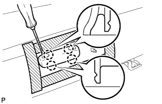
Using a screwdriver, detach the 4 claws and remove the knob.
Tech Tips
Tape the screwdriver tip before use.
-
-
REMOVE FRONT SEAT CUSHION SHIELD LH WITH FRONT INNER NO. 1 SEAT CUSHION SHIELD
-
Remove the 2 screws.
-
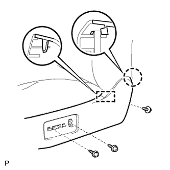
Remove the 3 screws.
-
Detach the claw and guide.
-
Remove the cushion shield.
-
-
REMOVE FRONT POWER SEAT SWITCH
-
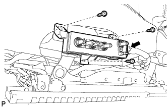
Remove the 3 screws.
-
Disconnect the connector and remove the switch.
-
-
REMOVE FRONT SEAT CUSHION INNER SHIELD LH
-
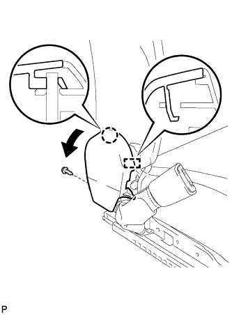
Remove the screw.
-
Pull the cushion inner shield to detach the claw and guide.
-
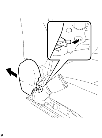
Pull the cushion inner shield to detach the claw and remove the cushion inner shield.
-
-
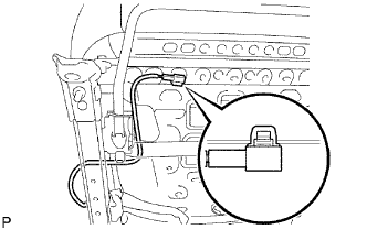
REMOVE FRONT SEAT INNER BELT ASSEMBLY LH
-
Detach the clamp.
-
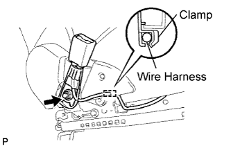
Detach the wire harness from the clamp.
-
Remove the nut and seat belt.
-
Remove the buckle cover.
-
-
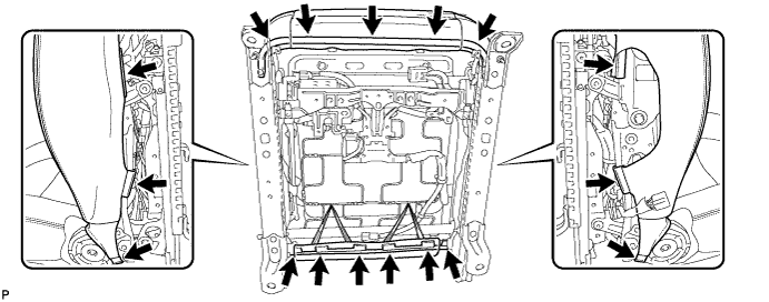
REMOVE SEAT CUSHION COVER WITH PAD
-
Remove the hog rings.
-
Detach the hooks and remove the seat cushion cover with pad.
-
-
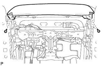
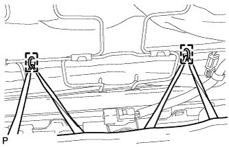
REMOVE FRONT POWER SEAT MOTOR ASSEMBLY (for Rear Lifter)
-
Detach the 2 wire harness clamps.
-
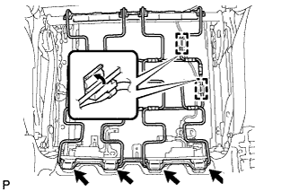
Detach the 4 clamps indicated by the arrows in the illustration and remove the seat cushion spring.
-
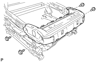
Remove the 4 bolts and seat cushion frame.
-

Using a T40 "TORX" socket wrench, remove the 2 "TORX" bolts for the tilt rod.
-
Remove the nut and tilt rod.
-

Disconnect the connector.
-
Using a T40 "TORX" socket wrench, remove the "TORX" bolt for the adjust screw.
-
Using a 4 mm socket hexagon wrench, remove the 2 bolts and motor.
Tech Tips
When the adjust screw is locked in the uppermost or lowermost position, turn the screw to release the lock before removing the motor unit.
-