UPPER INSTRUMENT PANEL INSTALLATION

Tech Tips
A bolt without a torque specification is shown in the standard bolt chart Click here.
-
INSTALL GLOVE COMPARTMENT DOOR LOCK ASSEMBLY
-
Install the glove compartment door lock with the 2 screws.
-
-
INSTALL UPPER INSTRUMENT PANEL SUB-ASSEMBLY
-
Attach the 5 guides and 8 claws to install the upper instrument panel.
-
Install the 2 bolts <A> and 2 screws <B>.
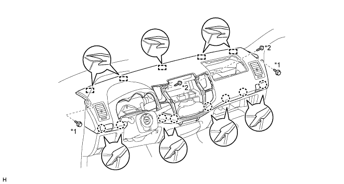
Text in Illustration *1 Bolt <A> *2 Screw <B>
-
-
INSTALL FRONT PILLAR GARNISH LH
-
Attach the 2 guides and 2 clips to install the front pillar garnish.
-
Install the front door opening trim.
-
-
INSTALL FRONT PILLAR GARNISH RH
Tech Tips
Use the same procedure described for the LH side.
-
INSTALL FRONT ASSIST GRIP SUB-ASSEMBLY
Tech Tips
Use the same procedure for both assist grip.
-
Install the assist grip with the 2 screws.
-
-
INSTALL FRONT NO. 1 ASSIST GRIP PLUG LH
Tech Tips
Use the same procedure for both front No. 1 assist grip plugs.
-
Attach the 2 claws to install the front No. 1 assist grip plug.
-
-
INSTALL FRONT NO. 1 ASSIST GRIP PLUG RH
Tech Tips
Use the same procedure described for the LH side.
-
INSTALL INSTRUMENT PANEL PASSENGER AIRBAG ASSEMBLY
-
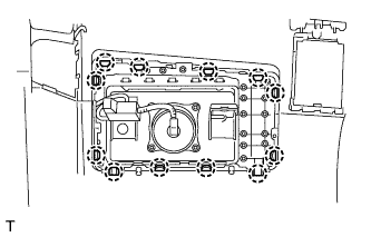
Attach the 12 claws to install the airbag.
-
Attach the clamp to the bracket.
-
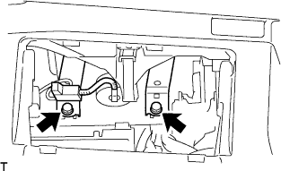
Tighten the 2 bolts.
- Torque:
- 20 N*m { 204 kgf*cm, 15 ft.*lbf }
-
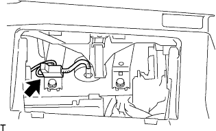
Connect the connector to the airbag.
Note
When handling the airbag connector, do not damage the airbag wire harness.
-
-
INSTALL GLOVE COMPARTMENT DOOR ASSEMBLY
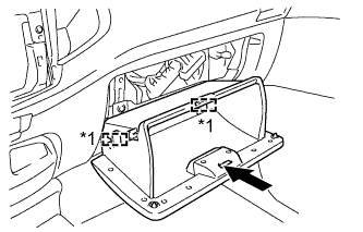
Text in Illustration *1 Hinge
-
Attach the 2 hinges to install the glove compartment door.
-
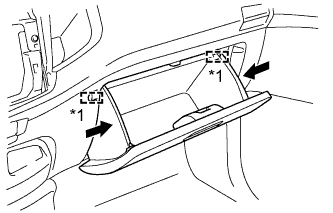
Text in Illustration *1 Stopper While pushing in the sides of the glove compartment door as indicated by the arrows in the illustration, close the door to engage it to the 2 stoppers.
-
-
INSTALL RADIO TUNER OPENING COVER (w/o Audio)
-
Install the radio tuner opening cover with the 4 screws.
-
-
INSTALL RADIO RECEIVER ASSEMBLY (w/ Audio)
-
for Radio Receiver Type:
-
for Radio and Display Type:
-
-
INSTALL CENTER INSTRUMENT CLUSTER FINISH PANEL ASSEMBLY
-
for Manual Air Conditioning System:
-
Connect the connectors.
-
Attach the 4 claws to connect the air conditioner control.
-
Attach the 10 claws and 4 clips to install the center instrument cluster finish panel.
-
-
for Automatic Air Conditioning System:
-
Connect the connectors.
-
Attach the 8 claws and 4 clips to install the center instrument cluster finish panel.
-
-
-
INSTALL COMBINATION METER ASSEMBLY
-
Connect the connectors and attach the clamp.
-
Install the combination meter with the 3 screws.
-
-
INSTALL NO. 1 INSTRUMENT CLUSTER FINISH PANEL
-
Attach the 2 claws and 3 guides to install the No. 1 instrument cluster finish panel.
-
Install the clip <C>.
-
-
INSTALL STEERING WHEEL ASSEMBLY
-
CONNECT CABLE TO NEGATIVE BATTERY TERMINAL
Note
When disconnecting the cable, some systems need to be initialized after the cable is reconnected Click here.
-
CHECK SRS WARNING LIGHT