UPPER INSTRUMENT PANEL DISASSEMBLY

-
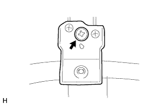
REMOVE METER MOUNTING BRACKET
-
Remove the screw <B> and meter mounting bracket.
-
-
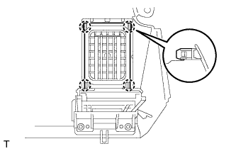
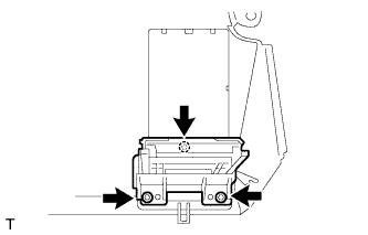
REMOVE NO. 2 INSTRUMENT PANEL REGISTER ASSEMBLY
-
Detach the 4 claws and remove the No. 2 instrument panel register.
-
-
REMOVE NO. 1 INSTRUMENT PANEL REGISTER ASSEMBLY
Tech Tips
Use the same procedure described for the No. 2 instrument panel register.
-
REMOVE INSTRUMENT PANEL CUP HOLDER SUB-ASSEMBLY
Tech Tips
Use the same procedure for both instrument panel cup holders.
-
Remove the 3 screws <B> and instrument panel cup holder.
-
-
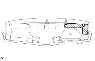
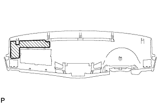
REMOVE NO. 4 INSTRUMENT PANEL CUSHION
-
Remove the No. 4 instrument panel cushion.
-
-
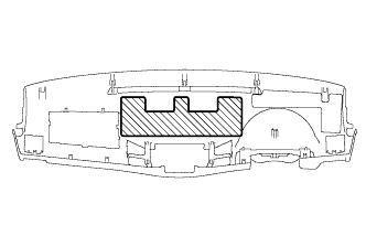
REMOVE NO. 3 INSTRUMENT PANEL CUSHION
-
Remove the No. 3 instrument panel cushion.
-
-
REMOVE NO. 2 INSTRUMENT PANEL CUSHION
-
Remove the No. 2 instrument panel cushion.
-
-
REMOVE AUTOMATIC LIGHT CONTROL SENSOR (w/ Automatic Light Control System)
-
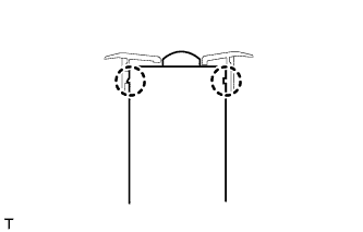
Detach the 2 claws and remove the automatic light control sensor.
-
-
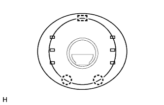
REMOVE LIGHT CONTROL SWITCH HOLE COVER (w/ Automatic Light Control System)
-
Detach the 2 claws and guide and remove the light control switch hole cover.
-
-
REMOVE COOLER (SOLAR SENSOR) THERMISTOR (for Automatic Air Conditioning System)
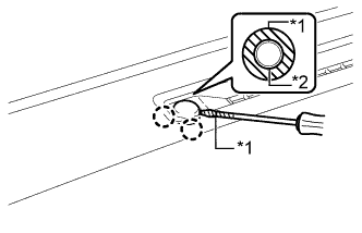
Text in Illustration *1 Protective Tape *2 Cooler Thermistor (Solar Sensor)
-
Put protective tape around the cooler thermistor (solar sensor).
-
Using a screwdriver, detach the 2 claws and remove the cooler thermistor (solar sensor).
Tech Tips
Tape the screwdriver tip before use.
-
Disconnect the connector.
-