UPPER INSTRUMENT PANEL REMOVAL

-
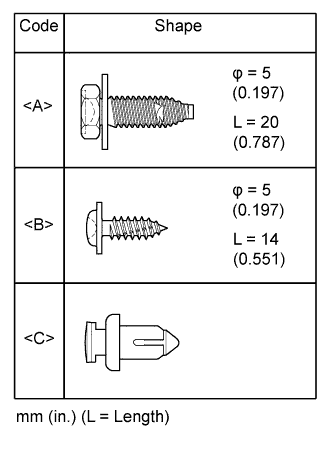
TABLE OF BOLT, SCREW AND NUT
-
All bolts, screws and clips relevant to installing and removing the instrument panel are shown along with their alphabetical code in the table.
-
-
PRECAUTION
Note
After turning the ignition switch off, waiting time may be required before disconnecting the cable from the battery terminal. Therefore, make sure to read the disconnecting the cable from the battery terminal notice before proceeding with work Click here.
-
DISCONNECT CABLE FROM NEGATIVE BATTERY TERMINAL
CAUTION:
Wait at least 90 seconds after disconnecting the cable from the negative (-) battery terminal to disable the SRS system.
Note
When disconnecting the cable, some systems need to be initialized after the cable is reconnected Click here.
-
REMOVE STEERING WHEEL ASSEMBLY
-
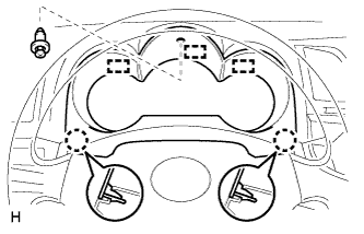
REMOVE NO. 1 INSTRUMENT CLUSTER FINISH PANEL
-
Remove the clip <C>.
-
Detach the 2 claws and 3 guides and remove the No. 1 instrument cluster finish panel.
-
-
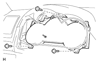
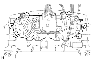
REMOVE COMBINATION METER ASSEMBLY
-
Remove the 3 screws.
-
Disconnect the connectors, detach the clamp and remove the combination meter.
-
-
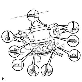
REMOVE CENTER INSTRUMENT CLUSTER FINISH PANEL ASSEMBLY
-
for Manual Air Conditioning System:
-
Put protective tape around the center instrument cluster finish panel.
-
Using a moulding remover, detach the 10 claws and 4 clips.
-
Text in Illustration *1 Protective Tape Detach the 4 claws and disconnect the air conditioner control.
-
Disconnect the connectors and remove the center instrument cluster finish panel.
-
-
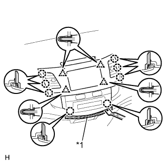
Text in Illustration *1 Protective Tape for Automatic Air Conditioning System:
-
Put protective tape around the center instrument cluster finish panel.
-
Using a moulding remover, detach the 8 claws and 4 clips.
-
Disconnect the connectors and remove the center instrument cluster finish panel.
-
-
-
REMOVE RADIO RECEIVER ASSEMBLY (w/ Audio)
-
for Radio Receiver Type:
-
for Radio and Display Type:
-
-
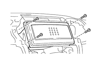
REMOVE RADIO TUNER OPENING COVER (w/o Audio)
-
Remove the 4 screws and radio tuner opening cover.
-
-
REMOVE GLOVE COMPARTMENT DOOR ASSEMBLY
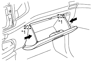
Text in Illustration *1 Stopper
-
Slightly bend the upper part of the glove compartment door to release the 2 stoppers and open the glove compartment door until it is horizontal.
-
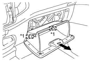
Text in Illustration *1 Hinge Pull the glove compartment door toward the rear of the vehicle to detach the 2 hinges and remove the glove compartment door.
-
-
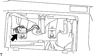
REMOVE INSTRUMENT PANEL PASSENGER AIRBAG ASSEMBLY
-
Disconnect the connector from the airbag.
Note
When handling the airbag connector, do not damage the airbag wire harness.
-
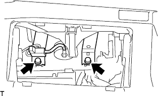
Remove the 2 bolts.
-
Detach the clamp from the bracket.
-
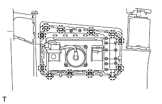
Detach the 12 claws and remove the airbag.
-
-
REMOVE FRONT NO. 1 ASSIST GRIP PLUG LH
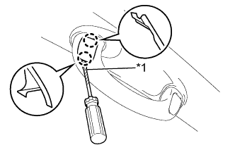
Text in Illustration *1 Protective Tape Tech Tips
Use the same procedure for both front No. 1 assist grip plugs.
-
Using a screwdriver, detach the 2 claws and remove the front No. 1 assist grip plug.
Tech Tips
Tape the screwdriver tip before use.
-
-
REMOVE FRONT NO. 1 ASSIST GRIP PLUG RH
Tech Tips
Use the same procedure described for the LH side.
-
REMOVE FRONT ASSIST GRIP SUB-ASSEMBLY
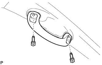
Tech Tips
Use the same procedure for both front assist grips.
-
Remove the 2 screws and front assist grip.
-
-
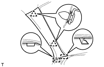
REMOVE FRONT PILLAR GARNISH LH
-
Remove the part of the front door opening trim attached to the front pillar garnish.
-
Detach the 2 clips and 2 guides and remove the front pillar garnish.
-
-
REMOVE FRONT PILLAR GARNISH RH
Tech Tips
Use the same procedure described for the LH side.
-
REMOVE UPPER INSTRUMENT PANEL SUB-ASSEMBLY
-
Put protective tape around the upper instrument panel.
-
Remove the 2 bolts <A> and 2 screws <B>.
-
Using a screwdriver, detach the 8 claws and 5 guides and remove the upper instrument panel.
Tech Tips
Tape the screwdriver tip before use.
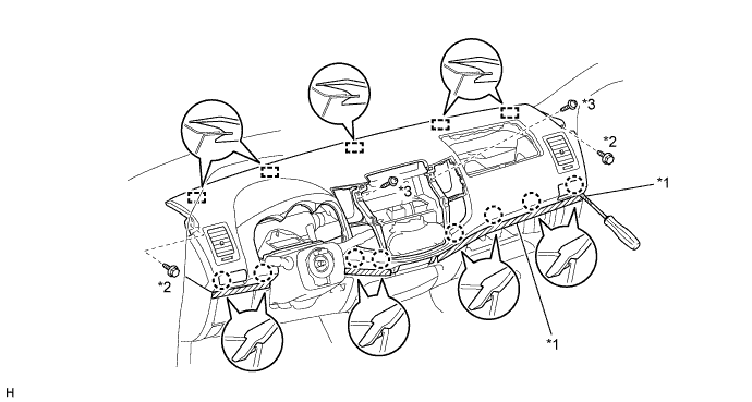
Text in Illustration *1 Protective Tape *2 Bolt <A> *3 Screw <B> - -
-
-
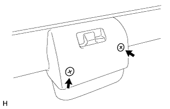
REMOVE GLOVE COMPARTMENT DOOR LOCK ASSEMBLY
-
Remove the 2 screws and glove compartment door lock.
-