POWER WINDOW CONTROL SYSTEM (w/o Jam Protection Function) Power Windows do not Operate at All
DESCRIPTION
If all of the power windows do not operate, the power window regulator master switch may have no power or may be malfunctioning.
WIRING DIAGRAM
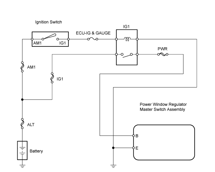
INSPECTION PROCEDURE
PROCEDURE
-
INSPECT FUSE (ECU-IG & GAUGE)
-
Remove the ECU-IG & GAUGE fuse from the instrument panel junction block.
-
Measure the resistance of the fuse.
Standard resistance Below 1 Ω
NG 
REPLACE FUSE
OK 
-
-
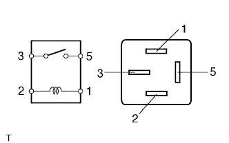
INSPECT IG1 RELAY (Marking: IG1)
-
Remove the IG1 relay from the No. 3 relay block.
-
Measure the resistance of the relay.
Standard resistance Tester Connection Specified Condition 3 - 5 10 kΩ or higher 3 - 5 Below 1 Ω
(when battery voltage is applied to terminals 1 and 2)
NG
REPLACE IG1 RELAY
OK
-
-
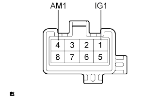
INSPECT IGNITION SWITCH ASSEMBLY
-
Remove the ignition switch.
-
Measure the resistance of the switch.
Standard resistance Tester Connection Switch Position Specified Condition 1 (IG1) - 4 (AM1) OFF 10 kΩ or higher 1 (IG1) - 4 (AM1) ON Below 1 Ω
NG
REPLACE IGNITION SWITCH ASSEMBLY
OK
-
-
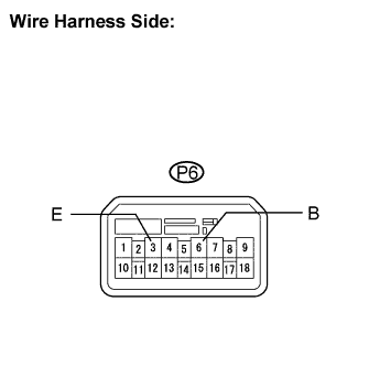
CHECK WIRE HARNESS (MASTER SWITCH - BATTERY AND BODY GROUND)
-
Disconnect the P6 master switch connector.
-
Measure the voltage of the wire harness side connectors.
Standard voltage Tester Connection Condition Specified Condition P6-6 (B) - Body ground Ignition switch ON 10 to 14 V -
Measure the resistance of the wire harness side connectors.
Standard resistance Tester Connection Specified Condition P6-3 (E) - Body ground Below 1 Ω
NG
REPAIR OR REPLACE HARNESS AND CONNECTOR
OK 
REPLACE POWER WINDOW REGULATOR MASTER SWITCH ASSEMBLY
-