POWER WINDOW CONTROL SYSTEM (w/o Jam Protection Function) Front Passenger Side Power Window does not Operate with Front Passenger Side Power Window Switch
DESCRIPTION
If the passenger side manual UP / DOWN function does not operate, a malfunction may be present in the power window regulator motor, power window regulator switch, power window regulator master switch or wire harness.
WIRING DIAGRAM
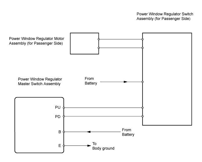
INSPECTION PROCEDURE
PROCEDURE
-
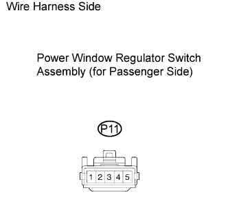
CHECK POWER WINDOW REGULATOR SWITCH ASSEMBLY (FOR PASSENGER SIDE) (POWER SOURCE)
-
Disconnect the P11 regulator switch connector.
-
Measure the voltage of the wire harness side connector.
Standard voltage Tester Connection Condition Specified Condition P11-3 - Body ground Ignition switch ON 10 to 14 V
NG 
REPAIR OR REPLACE HARNESS AND CONNECTOR
OK 
-
-
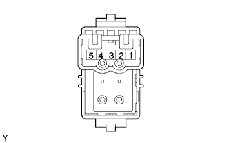
INSPECT POWER WINDOW REGULATOR SWITCH ASSEMBLY (FOR PASSENGER SIDE)
-
Remove the switch Click here.
-
Measure the resistance of the switch when the switch is operated.
Standard resistance Tester Connection Switch Condition Specified Condition 5 - 4
2 - 3
UP Below 1 Ω 5 - 4
2 - 1
OFF Below 1 Ω 5 - 3
2 - 1
DOWN Below 1 Ω
NG
REPLACE POWER WINDOW REGULATOR SWITCH ASSEMBLY
OK
-
-
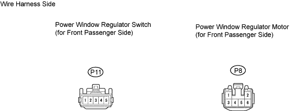
CHECK WIRE HARNESS (SWITCH (FOR PASSENGER SIDE) - MOTOR (FOR PASSENGER SIDE))
-
Disconnect the P11 switch connector.
-
Disconnect the P8 motor connector.
-
Measure the resistance of the wire harness side connectors.
Standard resistance Tester Connection Specified Condition P11-5 - P8-1 Below 1 Ω P11-2 - P8-2 Below 1 Ω P11-5 or P8-1 - Body ground 10 kΩ or higher P11-2 or P8-2 - Body ground 10 kΩ or higher
NG
REPAIR OR REPLACE HARNESS AND CONNECTOR
OK
-
-
INSPECT POWER WINDOW REGULATOR MOTOR ASSEMBLY (FOR PASSENGER SIDE)
-
Remove the motor Click here.
-
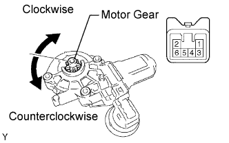
Apply battery voltage to connector terminals 1 and 2.
Note
Do not apply battery voltage to any terminals except terminals 1 and 2.
-
Check that the motor gear rotates smoothly as follows.
OK Measurement Condition Specified Condition Battery positive (+) → 1
Battery negative (-) → 2
Motor gear rotates clockwise Battery positive (+) → 2
Battery negative (-) → 1
Motor gear rotates counterclockwise
NG
REPLACE POWER WINDOW REGULATOR MOTOR ASSEMBLY
OK
-
-
CHECK WIRE HARNESS (MASTER SWITCH - SWITCH (FOR PASSENGER SIDE))
-
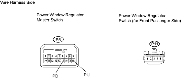
Disconnect the P6 master switch connector.
-
Disconnect the P11 switch connector.
-
Measure the resistance of the wire harness side connectors.
Standard resistance Tester Connection Specified Condition P6-18 (PU) - P11-1 Below 1 Ω P6-15 (PD) - P11-4 Below 1 Ω P6-18 (PU) or P11-1 - Body ground 10 kΩ or higher P6-15 (PD) or P11-4 - Body ground 10 kΩ or higher
NG
REPAIR OR REPLACE HARNESS AND CONNECTOR
OK
-
-
INSPECT POWER WINDOW REGULATOR MASTER SWITCH ASSEMBLY (FRONT PASSENGER SWITCH)
-
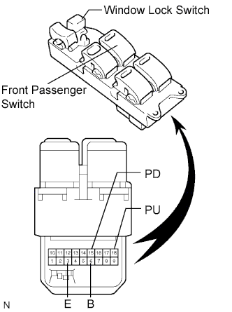
Remove the master switch Click here.
-
Measure the resistance of the switch when the switch is operated.
Standard resistance Window Lock Switch Condition Power Window Switch Condition Tester Connection Specified Condition OFF UP 3 (E) - 15 (PD)
6 (B) - 18 (PU)
Below 1 Ω OFF OFF 3 (E) - 18 (PU)
3 (E) - 15 (PD)
Below 1 Ω OFF DOWN 3 (E) - 18 (PU)
6 (B) - 15 (PD)
Below 1 Ω ON UP 3 (E) - 15 (PD) 10 kΩ or higher 6 (B) - 18 (PU) Below 1 Ω ON OFF 15 (PD) - 18 (PU) Below 1 Ω ON DOWN 3 (E) - 18 (PU) 10 kΩ or higher 6 (B) - 15 (PD) Below 1 Ω
NG
REPLACE POWER WINDOW REGULATOR MASTER SWITCH ASSEMBLY
OK 
GO TO POWER WINDOWS DO NOT OPERATE AT ALL
-