CLEARANCE SONAR MAIN SWITCH INSPECTION

-
INSPECT BACK SONAR OR CLEARANCE SONAR SWITCH ASSEMBLY
-
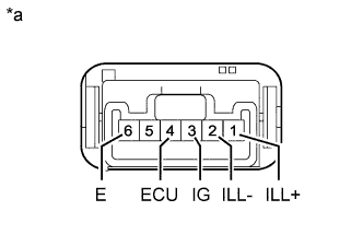
Text in Illustration *a Component without harness connected
(Back Sonar or Clearance Sonar Switch Assembly)
Resistance measurement of the back sonar or clearance sonar switch assembly.
-
Measure the resistance according to the value(s) in the table below.
Standard Resistance Tester Connection Switch Condition Specified Condition 3 (IG) - 4 (ECU) Back sonar or clearance sonar switch assembly pushed in Below 1 Ω Back sonar or clearance sonar switch assembly not pushed 10 kΩ or higher If the result is not as specified, replace the back sonar or clearance sonar switch assembly.
-
-
Inspect the illumination light.
-
Measure the resistance according to the value(s) in the table below.
Standard Resistance Tester Connection Switch Condition Specified Condition 1 (ILL+) - 2 (ILL-) Always Below 1 Ω 3 (IG) - 6 (E) Back sonar or clearance sonar switch assembly pushed in Below 1 Ω Back sonar or clearance sonar switch assembly not pushed 10 kΩ or higher If the result is not as specified, replace the bulb, and perform the on-vehicle inspection described above to inspect the illumination light again.
If the result is not as specified even when the bulb is replaced, replace the back sonar or clearance sonar switch assembly.
-
-