POWER WINDOW CONTROL SYSTEM (w/ Jam Protection Function) Auto Up / Down Function does not Operate
DESCRIPTION
If the auto up/down function does not operate, the cause may be one or more of the following:
-
The recorded power window fully closed position, which is stored in the power window regulator master switch assembly, was cleared as a result of: 1) the IG1 H-fuse, PWR H-fuse, DOOR fuse, ECU-IG&GAUGE fuse or IG1 relay being replaced; or 2) the battery cable and the master switch's connector being disconnected.
-
The power window regulator master switch assembly has a malfunction.
-
The pulse sensors in the front power window regulator motor assembly LH have a malfunction.
-
The wiring between the power window regulator master switch assembly and the front power window regulator motor assembly LH is open or short-circuited.
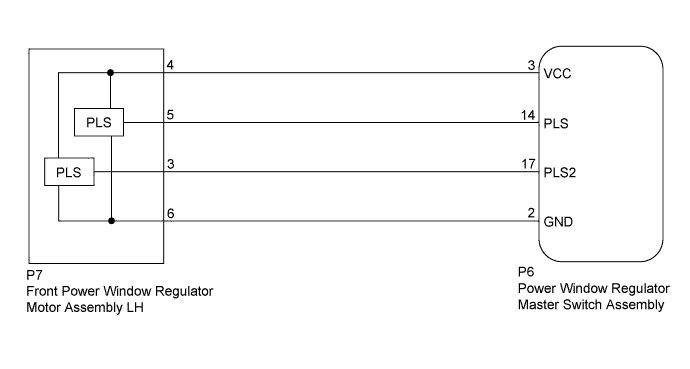
WIRING DIAGRAM
INSPECTION PROCEDURE
PROCEDURE
-
CHECK MANUAL UP/DOWN FUNCTION (FOR DRIVER SIDE)
-
Check that the manual up/down function operates normally.
OK Manual up/down function operates normally.
NG 
GO TO DRIVER SIDE POWER WINDOW MANUAL FUNCTION DOES NOT OPERATE WITH POWER WINDOW MASTER SWITCH Click here
OK 
-
-
PERFORM INITIALIZATION
-
Initialize the front power window regulator motor assembly LH Click here.
-
Check that the driver side door power window moves when the auto up and down functions of the power window regulator master switch assembly are operated Click here.
OK Driver side auto up and down functions are normal.
NG 
CHECK HARNESS AND CONNECTOR (POWER WINDOW REGULATOR MASTER SWITCH ASSEMBLY - FRONT POWER WINDOW REGULATOR MOTOR ASSEMBLY LH) Click here
OK 
END
-
-
CHECK HARNESS AND CONNECTOR (POWER WINDOW REGULATOR MASTER SWITCH ASSEMBLY - FRONT POWER WINDOW REGULATOR MOTOR ASSEMBLY LH)
-
Disconnect the P6 power window regulator master switch assembly connector.
-
Disconnect the P7 front power window regulator motor assembly LH connector.
-
Measure the resistance according to the value(s) in the table below.
Standard Resistance Tester Connection Condition Specified Condition P6-3 (VCC) - P7-4 Always Below 1 Ω P6-14 (PLS) - P7-5 Always Below 1 Ω P6-17 (PLS2) - P7-3 Always Below 1 Ω P6-2 (GND) - P7-6 Always Below 1 Ω P6-3 (VCC) or P7-4 - Body ground Always 10 kΩ or higher P6-14 (PLS) or P7-5 - Body ground Always 10 kΩ or higher P6-17 (PLS2) or P7-3 - Body ground Always 10 kΩ or higher
NG
REPAIR OR REPLACE HARNESS OR CONNECTOR
OK
-
-
CHECK POWER WINDOW REGULATOR MASTER SWITCH ASSEMBLY (PLS, PLS2 SIGNAL)
-
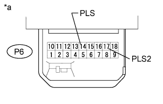
Text in Illustration *a Component with harness connected
(Power Window Regulator Master Switch Assembly)
Remove the power window regulator master switch assembly with its connectors still connected.
-
Using an oscilloscope, check the waveform.
OK Tester Connection Switch Condition Specified Condition P6-14 (PLS) - Body ground Ignition switch ON, driver side power window switch OFF → UP or DOWN Pulse waveform is output P6-17 (PLS2) - Body
NG
REPLACE FRONT POWER WINDOW REGULATOR MOTOR ASSEMBLY LH Click here
OK
REPLACE POWER WINDOW REGULATOR MASTER SWITCH ASSEMBLY Click here
-