TOYOTA PARKING ASSIST-SENSOR SYSTEM Clearance Warning Buzzer Circuit
DESCRIPTION
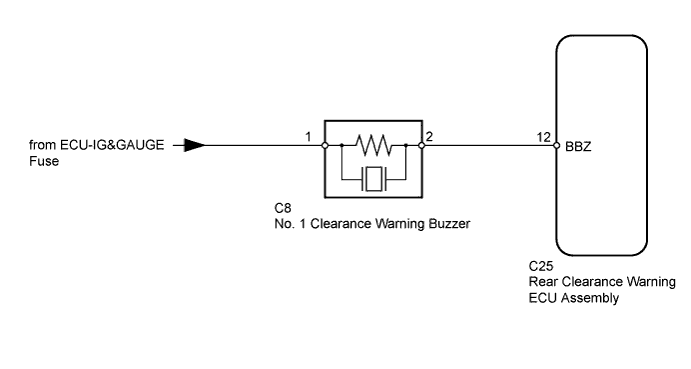
The rear clearance warning ECU assembly receives the No. 1 ultrasonic sensor signal to sound the No. 1 clearance warning buzzer.
WIRING DIAGRAM
INSPECTION PROCEDURE
PROCEDURE
-
CHECK HARNESS AND CONNECTOR (NO. 1 CLEARANCE WARNING BUZZER - REAR CLEARANCE WARNING ECU ASSEMBLY)
-

Disconnect the C8 No. 1 clearance warning buzzer connector.
-
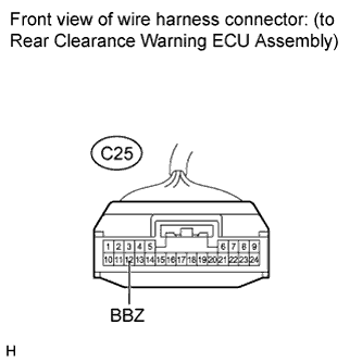
Disconnect the C25 rear clearance warning ECU assembly connector.
-
Measure the resistance according to the value(s) in the table below.
Standard Resistance Tester Connection Condition Specified Condition C8-2 - C25-12 (BBZ) Always Below 1 Ω C8-2 - Body ground Always 10 kΩ or higher
NG 
REPAIR OR REPLACE HARNESS OR CONNECTOR
OK 
-
-
CHECK HARNESS AND CONNECTOR (NO. 1 CLEARANCE WARNING BUZZER - BATTERY)
-
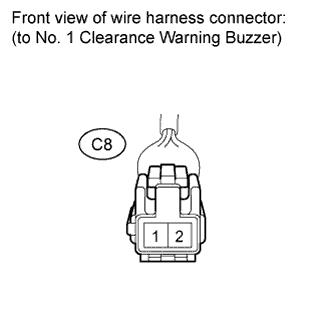
Disconnect the C8 No. 1 clearance warning buzzer connector.
-
Measure the voltage according to the value(s) in the table below.
Standard Voltage Tester Connection Switch Condition Specified Condition C8-1 - Body ground Ignition switch ON 11 to 14 V C8-1 - Body ground Ignition switch off Below 1 V
NG
REPAIR OR REPLACE HARNESS OR CONNECTOR
OK
-
-
REPLACE NO. 1 CLEARANCE WARNING BUZZER
-
Replace the No. 1 clearance warning buzzer Click here.
NEXT
-
-
CHECK NO. 1 CLEARANCE WARNING BUZZER OPERATION
-
Check that the No. 1 clearance warning buzzer sounds.
OK No. 1 clearance warning buzzer sounds.
NG
PROCEED TO NEXT SUSPECTED AREA SHOWN IN PROBLEM SYMPTOMS TABLE Click here
OK 
END (NO. 1 CLEARANCE WARNING BUZZER IS DEFECTIVE)
-