TOYOTA PARKING ASSIST-SENSOR SYSTEM Clearance Sonar Main Switch Circuit
DESCRIPTION
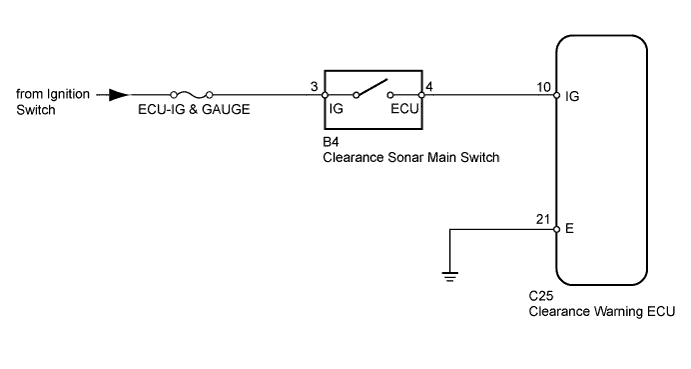
When the back sonar or clearance sonar switch assembly is turned on, an ON signal is sent to the clearance warning ECU, and the TOYOTA parking assist-sensor system starts operating.
WIRING DIAGRAM
INSPECTION PROCEDURE
PROCEDURE
-
INSPECT FUSE (ECU-IG&GAUGE)
-
Remove the ECU-IG&GAUGE fuse from the driver side junction block.
-
Measure the resistance according to the value(s) in the table below.
Standard Resistance Tester Connection Condition Specified Condition ECU-IG & GAUGE fuse Always Below 1 Ω
NG 
REPLACE FUSE
OK 
-
-
INSPECT BACK SONAR OR CLEARANCE SONAR SWITCH ASSEMBLY
-
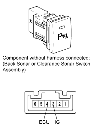
Remove the back sonar or clearance sonar switch assembly.
-
Measure the resistance according to the value(s) in the table below.
Standard Resistance Tester Connection Switch Condition Specified Condition 3 (IG) - 4 (ECU) Clearance sonar main switch on Below 1 Ω 3 (IG) - 4 (ECU) Clearance sonar main switch off 10 kΩ or higher
NG
REPLACE BACK SONAR OR CLEARANCE SONAR SWITCH ASSEMBLY
OK
-
-
CHECK HARNESS AND CONNECTOR (BACK SONAR OR CLEARANCE SONAR SWITCH ASSEMBLY - REAR CLEARANCE WARNING ECU ASSEMBLY)
-
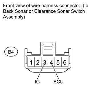
Disconnect the B4 back sonar or clearance sonar switch assembly connector.
-
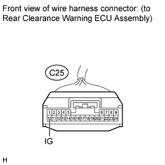
Disconnect the C25 rear clearance warning ECU assembly connector.
-
Measure the voltage according to the value(s) in the table below.
Standard Voltage Tester Connection Switch Condition Specified Condition B4-3 (IG) - Body ground Ignition switch ON 11 to 14 V B4-3 (IG) - Body ground Ignition switch off Below 1 V -
Measure the resistance according to the value(s) in the table below.
Standard Resistance Tester Connection Condition Specified Condition B4-4 (ECU) - C25-10 (IG) Always Below 1 Ω B4-4 (ECU) - Body ground Always 10 kΩ or higher
NG
REPAIR OR REPLACE HARNESS OR CONNECTOR
OK
-
-
CHECK HARNESS AND CONNECTOR (REAR CLEARANCE WARNING ECU ASSEMBLY - BODY GROUND)
-
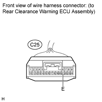
Disconnect the C25 rear clearance warning ECU assembly connector.
-
Measure the resistance according to the value(s) in the table below.
Standard Resistance Tester Connection Condition Specified Condition C25-21 (E) - Body ground Always Below 1 Ω
NG
REPAIR OR REPLACE HARNESS OR CONNECTOR
OK 
PROCEED TO NEXT SUSPECTED AREA SHOWN IN PROBLEM SYMPTOMS TABLE Click here
-