TOYOTA PARKING ASSIST-SENSOR SYSTEM Back Sonar Sensor Circuit
DESCRIPTION
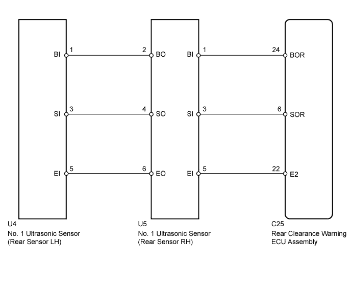
This circuit includes the sensor power supply, sensor ground, and sensor signal wires between the rear clearance warning ECU assembly and No. 1 ultrasonic sensors. The No. 1 ultrasonic sensors are digital sensors.
WIRING DIAGRAM
INSPECTION PROCEDURE
PROCEDURE
-
CHECK REAR CLEARANCE WARNING ECU ASSEMBLY
-

Measure the resistance according to the value(s) in the table below.
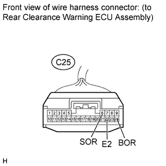
Standard Resistance Tester Connection Condition Specified Condition C25-22 (E2) - Body ground Always Below 1 Ω -
Measure the voltage according to the value(s) in the table below.
Standard Voltage Tester Connection Switch Condition Specified Condition C25-24 (BOR) - C25-22 (E2) Ignition switch ON, back sonar or clearance sonar switch on 7.2 to 8.8 V
NG 
REPLACE REAR CLEARANCE WARNING ECU ASSEMBLY Click here
OK 
-
-
CHECK HARNESS AND CONNECTOR (REAR CLEARANCE WARNING ECU ASSEMBLY - REAR SENSOR RH)
-
Disconnect the C25 rear clearance warning ECU assembly connector.
-
Disconnect the U5 No. 1 ultrasonic sensor (rear sensor RH) connector.
-
Measure the resistance according to the value(s) in the table below.
Standard Resistance Tester Connection Condition Specified Condition C25-24 (BOR) - U5-1 (BI) Always Below 1 Ω C25-6 (SOR) - U5-3 (SI) Always Below 1 Ω C25-22 (E2) - U5-5 (EI) Always Below 1 Ω C25-24 (BOR) - Body ground Always 10 kΩ or higher C25-6 (SOR) - Body ground Always 10 kΩ or higher C25-22 (E2) - Body ground Always 10 kΩ or higher
NG
REPAIR OR REPLACE HARNESS OR CONNECTOR
OK
-
-
CHECK HARNESS AND CONNECTOR (REAR SENSOR RH - REAR SENSOR LH)
-
Disconnect the U5 No . 1 ultrasonic sensor (rear sensor RH) connector.
-

Disconnect the U4 No. 1 ultrasonic sensor (rear sensor LH) connector.
-
Measure the resistance according to the value(s) in the table below.
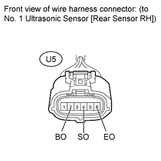
Standard Resistance Tester Connection Condition Specified Condition U5-2 (BO) - U4-1 (BI) Always Below 1 Ω U5-4 (SO) - U4-3 (SI) Always Below 1 Ω U5-6 (EO) - U4-5 (EI) Always Below 1 Ω U5-2 (BO) - Body ground Always 10 kΩ or higher U5-4 (SO) - Body ground Always 10 kΩ or higher U5-6 (EO) - Body ground Always 10 kΩ or higher
NG
REPAIR OR REPLACE HARNESS OR CONNECTOR
OK
-
-
INSPECT NO. 1 ULTRASONIC SENSOR (REAR SENSOR RH)
-
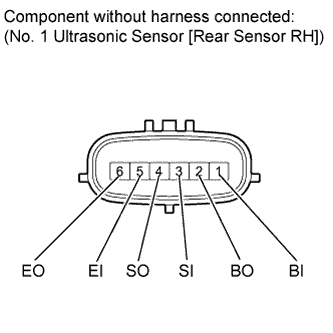
Remove the No. 1 ultrasonic sensor (rear sensor RH) Click here.
-
Measure the resistance according to the value(s) in the table below.
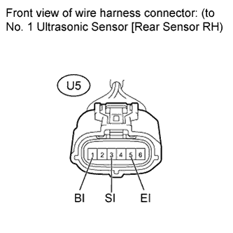
Standard Resistance Tester Connection Condition Specified Condition 1 (BI) - 5 (EI) Always 10 kΩ or higher 1 (BI) - 2 (BO) Always 10 kΩ or higher 3 (SI) - 4 (SO) Always Below 1 Ω 5 (EI) - 6 (EO) Always Below 1 Ω
NG
REPLACE NO. 1 ULTRASONIC SENSOR (REAR SENSOR RH) Click here
OK
-
-
CHECK TOYOTA PARKING ASSIST-SENSOR SYSTEM
-
Check the operation of the TOYOTA parking assist-sensor system Click here.
Result Result Proceed to TOYOTA parking assist-sensor system malfunction A TOYOTA parking assist-sensor system normal operation B
B
END
A
-
-
REPLACE NO. 1 ULTRASONIC SENSOR (REAR SENSOR LH)
-
Replace the No. 1 ultrasonic sensor (rear sensor LH) Click here.
NEXT
-
-
CHECK TOYOTA PARKING ASSIST-SENSOR SYSTEM
-
Check the operation of the TOYOTA parking assist-sensor system Click here.
Result Result Proceed to TOYOTA parking assist-sensor system malfunction A TOYOTA parking assist-sensor system normal operation B
B
END (NO. 1 ULTRASONIC SENSOR LH IS DEFECTIVE)
A
-
-
REPLACE NO. 1 ULTRASONIC SENSOR (REAR SENSOR RH)
-
Replace the No. 1 ultrasonic sensor (rear sensor RH) Click here.
NEXT
-
-
CHECK TOYOTA PARKING ASSIST-SENSOR SYSTEM
-
Check the operation of the TOYOTA parking assist-sensor system Click here.
Result Result Proceed to TOYOTA parking assist-sensor system malfunction A TOYOTA parking assist-sensor system normal operation B
NG
END (NO. 1 ULTRASONIC SENSOR RH IS DEFECTIVE)
OK 
PROCEED TO NEXT SUSPECTED AREA SHOWN IN PROBLEM SYMPTOMS TABLE Click here
-