TOYOTA PARKING ASSIST-SENSOR SYSTEM Speed Signal Circuit
DESCRIPTION
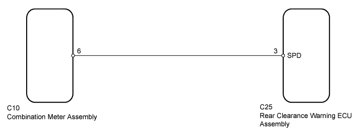
The rear clearance warning ECU assembly receives the vehicle speed signal from the combination meter assembly.
WIRING DIAGRAM
INSPECTION PROCEDURE
PROCEDURE
-
CHECK COMBINATION METER ASSEMBLY (SPEEDOMETER)
-
Drive the vehicle and check if the function of the speedometer on the combination meter is normal.
OK Actual vehicle speed and the speed indicated on the speedometer are the same.
NG 
GO TO METER / GAUGE SYSTEM Click here
OK 
-
-
CHECK REAR CLEARANCE WARNING ECU ASSEMBLY
-
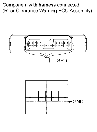
Using an oscilloscope, check the waveform.
Measurement Condition Item Content Tester Connection C25-3 (SPD) - Body ground Tool Setting 5 V/DIV., 10 msec./DIV. Condition Vehicle driven at approximately 20 km/h (12.4 mph) OK Correct waveform is as shown.
NG 
CHECK HARNESS AND CONNECTOR (REAR CLEARANCE WARNING ECU ASSEMBLY - COMBINATION METER ASSEMBLY) Click here
OK 
PROCEED TO NEXT SUSPECTED AREA SHOWN IN PROBLEM SYMPTOMS TABLE Click here
-
-
CHECK HARNESS AND CONNECTOR (REAR CLEARANCE WARNING ECU ASSEMBLY - COMBINATION METER ASSEMBLY)
-
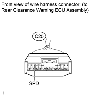
Disconnect the C25 rear clearance warning ECU assembly connector.
-
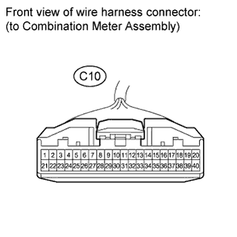
Disconnect the C10 combination meter assembly connector.
-
Measure the resistance according to the value(s) in the table below.
Standard Resistance Tester Connection Condition Specified Condition C25-3 (SPD) - C10-6 Always Below 1 Ω C25-3 (SPD) - Body ground Always 10 kΩ or higher
NG
REPAIR OR REPLACE HARNESS OR CONNECTOR
OK
REPLACE COMBINATION METER ASSEMBLY Click here
-