TOYOTA PARKING ASSIST-SENSOR SYSTEM Back-up Light Circuit
DESCRIPTION
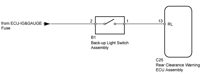
This circuit sends the back-up light switch assembly signals to the rear clearance warning ECU assembly.
WIRING DIAGRAM
INSPECTION PROCEDURE
PROCEDURE
-
SELECT ENGINE TYPE
-
Select the engine type.
Result Result Proceed to 1GR - FE A 2TR - FE B
B 
INSPECT BACK-UP LIGHT SWITCH ASSEMBLY Click here
A 
-
-
INSPECT BACK-UP LIGHT SWITCH ASSEMBLY
-
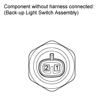
Disconnect the B1 back-up light switch assembly connector.
-
Measure the resistance according to the value(s) in the table below.
Standard Resistance Tester Connection Condition Specified Condition 1 - 2 Shift lever on R Below 1 Ω 1 - 2 Shift lever not on R 10 kΩ or higher
NG 
REPLACE BACK-UP LIGHT SWITCH ASSEMBLY Click here
OK
-
-
CHECK HARNESS AND CONNECTOR (BACK-UP LIGHT SWITCH ASSEMBLY - REAR CLEARANCE WARNING ECU ASSEMBLY)
-
Disconnect the B1 back-up light switch assembly connector.
-
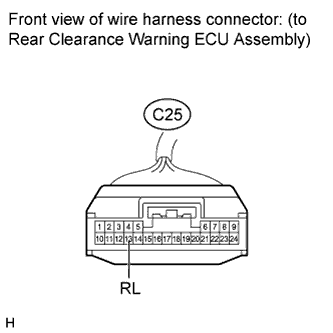
Disconnect the C25 rear clearance warning ECU assembly connector.
-
Measure the voltage according to the value(s) in the table below.
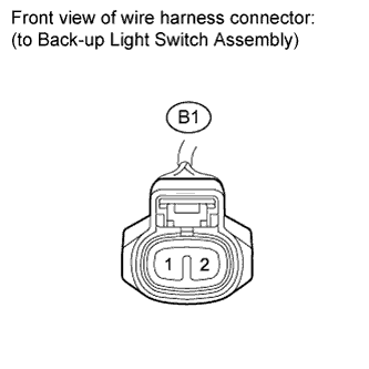
Standard Voltage Tester Connection Switch Condition Specified Condition B1-2 - Body ground Ignition switch ON 11 to 14 V B1-2 - Body ground Ignition switch off Below 1 V -
Measure the resistance according to the value(s) in the table below.
Standard Resistance Tester Connection Condition Specified Condition B1-1 - C25-13 (RL) Always Below 1 Ω B1-1 - Body ground Always 10 kΩ or higher
NG
REPAIR OR REPLACE HARNESS OR CONNECTOR
OK 
PROCEED TO NEXT SUSPECTED AREA SHOWN IN PROBLEM SYMPTOMS TABLE Click here
-
-
INSPECT BACK-UP LIGHT SWITCH ASSEMBLY
-
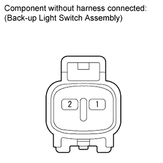
Disconnect the B1 back-up light switch assembly connector.
-
Measure the resistance according to the value(s) in the table below.
Standard Resistance Tester Connection Condition Specified Condition 1 - 2 Shift lever on R Below 1 Ω 1 - 2 Shift lever not on R 10 kΩ or higher Result Result Proceed to OK A NG (R150) B NG (R150F) C
B
REPLACE BACK-UP LIGHT SWITCH ASSEMBLY Click here
C
REPLACE BACK-UP LIGHT SWITCH ASSEMBLY Click here
A
-
-
CHECK HARNESS AND CONNECTOR (BACK-UP LIGHT SWITCH ASSEMBLY - REAR CLEARANCE WARNING ECU ASSEMBLY)
-
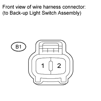
Disconnect the B1 back-up light switch assembly connector.
-
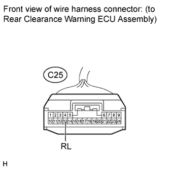
Disconnect the C25 rear clearance warning ECU assembly connector.
-
Measure the voltage according to the value(s) in the table below.
Standard Voltage Tester Connection Switch Condition Specified Condition B1-2 - Body ground Ignition switch ON 11 to 14 V B1-2 - Body ground Ignition switch off Below 1 V -
Measure the resistance according to the value(s) in the table below.
Standard Resistance Tester Connection Condition Specified Condition B1-1 - C25-13 (RL) Always Below 1 Ω B1-1 - Body ground Always 10 kΩ or higher
NG
REPAIR OR REPLACE HARNESS OR CONNECTOR
OK
PROCEED TO NEXT SUSPECTED AREA SHOWN IN PROBLEM SYMPTOMS TABLE Click here
-