TOYOTA PARKING ASSIST-SENSOR SYSTEM Park / Neutral Position Switch Circuit
DESCRIPTION
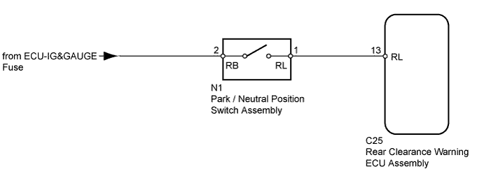
This circuit sends the park/neutral position switch assembly signals to the rear clearance warning ECU assembly.
WIRING DIAGRAM
INSPECTION PROCEDURE
PROCEDURE
-
INSPECT PARK/NEUTRAL POSITION SWITCH ASSEMBLY
-
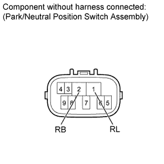
Disconnect the N1 park/neutral position switch assembly connector.
-
Measure the resistance according to the value(s) in the table below.
Standard Resistance Tester Connection Condition Specified Condition 1 (RL) - 2 (RB) Shift lever on R Below 1 Ω 1 (RL) - 2 (RB) Shift lever not on R 10 kΩ or higher Result Result Proceed to OK A NG (A343F) B NG (A750F) C NG (A343E) D
B 
REPLACE PARK / NEUTRAL POSITION SWITCH Click here
C
REPLACE PARK / NEUTRAL POSITION SWITCH Click here
D
REPLACE PARK / NEUTRAL POSITION SWITCH Click here
A 
-
-
CHECK HARNESS AND CONNECTOR (PARK/NEUTRAL POSITION SWITCH ASSEMBLY - REAR CLEARANCE WARNING ECU ASSEMBLY)
-
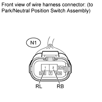
Disconnect the N1 park/neutral position switch assembly connector.
-
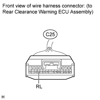
Disconnect the C25 rear clearance warning ECU assembly connector.
-
Measure the voltage according to the value(s) in the table below.
Standard Voltage Tester Connection Switch Condition Specified Condition N1-2 (RB) - Body ground Ignition switch ON 11 to 14 V N1-2 (RB) - Body ground Ignition switch off Below 1 V -
Measure the resistance according to the value(s) in the table below.
Standard Resistance Tester Connection Condition Specified Condition N1-1 (RL) - C25-13 (RL) Always Below 1 Ω N1-1 (RL) - Body ground Always 10 kΩ or higher
NG
REPAIR OR REPLACE HARNESS OR CONNECTOR
OK 
PROCEED TO NEXT SUSPECTED AREA SHOWN IN PROBLEM SYMPTOMS TABLE Click here
-