TOYOTA PARKING ASSIST-SENSOR SYSTEM TERMINALS OF ECU

-
CHECK CLEARANCE WARNING ECU

-
Disconnect the C25 ECU connector.
-
Measure the voltage and resistance according to the value(s) in the table below.
Terminal No. (Symbols) Wiring Color Terminal Description Condition Specified Condition C25-10 (IG) - Body ground L-R - Body ground IG power source circuit Ignition switch ON, clearance sonar main switch on 11 to 14 V C25-10 (IG) - Body ground L-R - Body ground IG power source circuit Ignition switch ON, clearance sonar main switch off Below 1 V C25-21 (E) - Body ground W-B - Body ground Body ground Always Below 1 Ω If the result is not as specified, there may be a malfunction on the wire harness side.
-
Reconnect the C25 ECU connector.
-
Measure the voltage according to the value(s) in the table below.
Terminal No. (Symbols) Wiring Color Terminal Description Condition Specified Condition C25-13 (RL) - Body ground R-W - Body ground Reverse position signal Ignition switch ON, shift lever moved to R 7 V or higher C25-13 (RL) - Body ground R-W - Body ground Reverse position signal Ignition switch ON, shift lever moved to any position except R Below 1 V C25-12 (BBZ) - Body ground P-G - Body ground No. 1 clearance warning buzzer signal Sonar detects obstacle (buzzer sounds) Waveform 1 C25-3 (SPD) - Body ground V-R - Body ground Vehicle speed signal Vehicle driven at approximately 20 km/h (12 mph) Waveform 2 C25-22 (E2) - Body ground L - Body ground No. 1 ultrasonic sensor ground Always Below 1 V C25-24 (BOR) - C25-22 (E2) BR - L No. 1 ultrasonic sensor power source circuit Ignition switch ON, clearance sonar main switch on 7.2 to 8.8 V C25-24 (BOR) - C25-22 (E2) BR - L No. 1 ultrasonic sensor power source circuit Ignition switch off Below 1.5 V C25-6 (SOR) - C25-22 (E2) P - L No. 1 ultrasonic sensor communication signal Ignition switch ON, clearance sonar main switch on Waveform 3 If the result is not as specified, the ECU may have a malfunction.
-
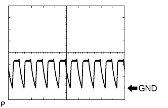
Using an oscilloscope, check waveform 1.
Measurement Condition Item Content Terminal No. (Symbols) C25-12 (BBZ) - Body ground Tool Setting 5 V/DIV., 1 msec./DIV. Condition Sonar detects obstacle (buzzer sounds) -
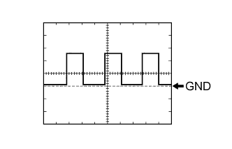
Using an oscilloscope, check waveform 2.
Measurement Condition Item Content Terminal No. (Symbols) C25-3 (SPD) - Body ground Tool Setting 5 V/DIV., 10 msec./DIV. Condition Vehicle driven at approximately 20 km/h (12.4 mph) -
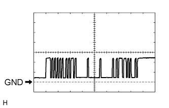
Using an oscilloscope, check waveform 3.
Measurement Condition Item Content Terminal No. (Symbols) C25-6 (SOR) - C25-22 (E2) Tool Setting 2 V/DIV., 200 μsec./DIV. Condition Ignition switch ON, clearance sonar main switch on
-
-