REAR VIEW MONITOR SYSTEM, Diagnostic DTC:C1622

| DTC Code | DTC Name |
|---|---|
| C1622 | Open or Short Circuit in Back Camera Signal |
DESCRIPTION
This DTC is stored if the radio and display receiver assembly judges as a result of its self check that the signals or signal lines between the radio and display receiver assembly and the rear television camera assembly are not normal.
| DTC Code | DTC Detection Condition | Trouble Area |
|---|---|---|
| C1622 | Open or Short Circuit in rear television camera signal |
|
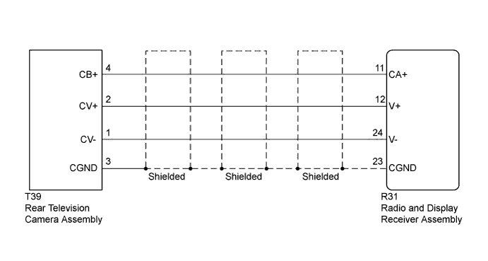
WIRING DIAGRAM
INSPECTION PROCEDURE
PROCEDURE
-
CHECK FOR DTC
-
Clear the DTCs Click here.
-
Check for DTCs Click here.
Result Result Proceed to No DTC is output A DTC is output B
B 
CHECK HARNESS AND CONNECTOR (RADIO AND DISPLAY RECEIVER ASSEMBLY - REAR TELEVISION CAMERA ASSEMBLY) Click here
A 
USE SIMULATION METHOD TO CHECK Click here
-
-
CHECK HARNESS AND CONNECTOR (RADIO AND DISPLAY RECEIVER ASSEMBLY - REAR TELEVISION CAMERA ASSEMBLY)
-
Disconnect the R31 radio and display receiver assembly connector.
-
Disconnect the T39 rear television camera assembly connector.
-
Measure the resistance according to the value(s) in the table below.
Standard Resistance Tester Connection Condition Specified Condition R31-11 (CA+) - T39-4 (CB+) Always Below 1 Ω R31-12 (V+) - T39-2 (CV+) Always Below 1 Ω R31-23 (CGND) - T39-3 (CGND) Always Below 1 Ω R31-24 (V-) - T39-1 (CV-) Always Below 1 Ω R31-11 (CA+) - Body ground Always 10 kΩ or higher R31-12 (V+) - Body ground Always 10 kΩ or higher R31-23 (CGND) - Body ground Always 10 kΩ or higher R31-24 (V-) - Body ground Always 10 kΩ or higher
NG 
REPAIR OR REPLACE HARNESS OR CONNECTOR
OK 
-
-
INSPECT RADIO AND DISPLAY RECEIVER ASSEMBLY
-
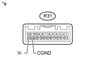
Text in Illustration *a Component without harness connected
(Radio and Display Receiver Assembly)
Disconnect the R31 radio and display receiver assembly connector.
-
Measure the resistance according to the value(s) in the table below.
Standard Resistance Tester Connection Condition Specified Condition R31-23 (CGND) - Body ground Always Below 1 Ω R31-24 (V-) - Body ground Always Below 1 Ω
NG
REPLACE RADIO AND DISPLAY RECEIVER ASSEMBLY Click here
OK
-
-
CHECK RADIO AND DISPLAY RECEIVER ASSEMBLY
-
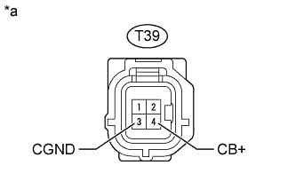
Text in Illustration *a Front view of wire harness connector
(to Rear Television Camera Assembly)
Disconnect the T39 rear television camera assembly connector.
-
Measure the voltage according to the value(s) in the table below.
Standard Voltage Tester Connection Switch Condition Specified Condition T39-4 (CB+) - T39-3 (CGND) Ignition switch ACC 5.5 to 7.05 V
NG
REPLACE RADIO AND DISPLAY RECEIVER ASSEMBLY Click here
OK
-
-
CHECK REAR TELEVISION CAMERA ASSEMBLY
-
Using an oscilloscope, check the waveform.
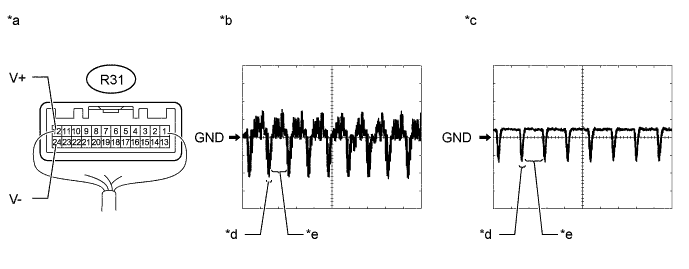
Text in Illustration *a Component with harness connected
(Radio and Display Receiver Assembly)
*b Waveform 1 *c Waveform 2 *d Synchronized Signal *e Video Waveform - - Measurement Condition Item Content Tester Connection R31-12 (V+) - R31-24 (V-) Tool Setting 0.2 V/DIV., 50 μs/DIV. Condition
-
Waveform 1: Ignition switch ON, shift lever in R
-
Waveform 2: Ignition switch ON, shift lever in R, screen blacked out by covering camera lens
OK Waveform is as shown in illustration. Tech Tips
The video waveform changes according to the image sent by the rear television camera assembly.
-
NG
REPLACE REAR TELEVISION CAMERA ASSEMBLY Click here
OK
USE SIMULATION METHOD TO CHECK Click here
-
-
REPLACE REAR TELEVISION CAMERA ASSEMBLY
-
Replace the rear television camera assembly with a new or normally functioning one Click here.
NEXT
-
-
CHECK FOR DTC
-
Clear the DTCs Click here.
-
Check for DTCs Click here.
Result Result Proceed to No DTC is output A DTC is output B
B
REPLACE RADIO AND DISPLAY RECEIVER ASSEMBLY Click here
A
END (REAR TELEVISION CAMERA ASSEMBLY WAS DEFECTIVE)
-