AUDIO AND VISUAL SYSTEM (for Radio and Display Type) Microphone Circuit between Microphone and Radio Receiver
DESCRIPTION
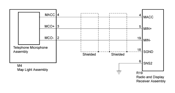
Microphone signal from the telephone microphone assembly is sent to the radio and display receiver assembly. Also, power is supplied from the radio and display receiver assembly to the telephone microphone assembly.
WIRING DIAGRAM
INSPECTION PROCEDURE
PROCEDURE
-
CHECK MICROPHONE (OPERATION CHECK)
-
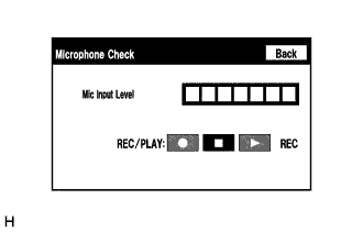
Enter the "Microphone Check" screen. [Refer to Microphone and Voice Recognition Check in Operation Check Click here].
-
When a voice is input into the microphone, check that the microphone input level meter changes according to the input voice.
-
w/ Recording Function:
-
Push the recording switch and perform voice recording.
Tech Tips
-
Select the recording switch with the blower motor of the air conditioning system stopped. If an outlet of the air conditioning system is facing the microphone, noise may be recorded
-
Voice can be recorded for up to 5 seconds.
-
-
-
Check that the recording indicator remains on while recording and that the recorded voice is played normally without noise or distortion.
OK All check results are normal.
NG 
CHECK HARNESS AND CONNECTOR (RADIO AND DISPLAY RECEIVER - MAP LIGHT) Click here
OK 
REPLACE RADIO AND DISPLAY RECEIVER ASSEMBLY Click here
-
-
CHECK HARNESS AND CONNECTOR (RADIO AND DISPLAY RECEIVER - MAP LIGHT)
-
Disconnect the R19 radio and display receiver assembly connector.
-
Disconnect the M4 map light assembly connector.
-
Measure the resistance according to the value(s) in the table below.
Standard Resistance Tester Connection Condition Specified Condition R19-4 (MACC) - M4-4 (MACC) Always Below 1 Ω R19-5 (MIN+) - M4-3 (MCO+) R19-19 (MIN-) - M4-2 (MCO-) R19-6 (SNS2) - Body ground R19-4 (MACC) - Body ground Always 10 kΩ or higher R19-5 (MIN+) - Body ground R19-19 (MIN-) - Body ground R19-18 (SGND) - Body ground
NG 
REPAIR OR REPLACE HARNESS OR CONNECTOR
OK 
-
-
CHECK RADIO AND DISPLAY RECEIVER ASSEMBLY
-
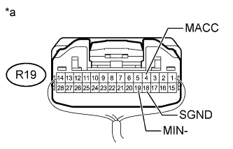
Text in Illustration *a Component with harness connected
(Radio and Display Receiver Assembly)
Measure the resistance according to the value(s) in the table below.
Standard Resistance Tester Connection Condition Specified Condition R19-18 (SGND) - Body ground Always Below 1 Ω R19-19 (MIN-) - Body ground -
Measure the voltage according to the value(s) in the table below.
Standard Voltage Tester Connection Switch Condition Specified Condition R19-4 (MACC) - Body ground Ignition switch ACC 4 to 6 V
NG
REPLACE RADIO AND DISPLAY RECEIVER ASSEMBLY Click here
OK
-
-
REPLACE TELEPHONE MICROPHONE WITH ANOTHER AND CHECK
-
Replace the telephone microphone with a known good one Click here.
-
Check that the malfunction disappears.
OK Malfunction disappears.
NG
REPLACE MAP LIGHT ASSEMBLY Click here
OK
END (TELEPHONE MICROPHONE ASSEMBLY IS DEFECTIVE)
-