AUDIO AND VISUAL SYSTEM (for Radio and Display Type), Diagnostic DTC:B15C3

| DTC Code | DTC Name |
|---|---|
| B15C3 | Speaker Output Short |
DESCRIPTION
This DTC is stored when a malfunction occurs in the speakers.
| DTC Code | DTC Detection Condition | Trouble Area |
|---|---|---|
| B15C3 | A short is detected in the speaker output circuit. |
|
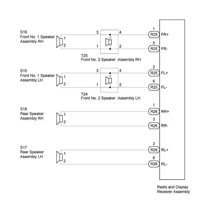
WIRING DIAGRAM
INSPECTION PROCEDURE
PROCEDURE
-
CHECK FOR DTC
-
Disconnect the R25 and R26 radio and display receiver assembly connectors.
-
Clear the DTC Click here.
-
Check if DTC B15C3 is output.
OK DTC B15C3 is not output.
NG 
REPLACE RADIO AND DISPLAY RECEIVER ASSEMBLY Click here
OK 
-
-
CHECK FOR DTC
-
Reconnect the R26 radio and display receiver assembly connector.
-
Clear the DTC Click here.
-
Check if DTC B15C3 is output.
OK DTC B15C3 is not output.
NG 
CHECK HARNESS AND CONNECTOR (RADIO AND DISPLAY RECEIVER - REAR SPEAKER) Click here
OK
-
-
CHECK HARNESS AND CONNECTOR (RADIO AND DISPLAY RECEIVER - FRONT NO. 2 SPEAKER)
-
Disconnect the R25 radio and display receiver assembly connector.
-
Disconnect the T25*1 and/or T24*2 speaker connector.
-
*1: for RH
-
*2: for LH
-
-
Measure the resistance according to the value(s) in the table below.
Standard Resistance for RH Tester Connection Condition Specified Condition R25-1 (FR+) - T25-4 Always Below 1 Ω R25-5 (FR-) - T25-2 R25-1 (FR+) - Body ground Always 10 kΩ or higher R25-5 (FR-) - Body ground for LH Tester Connection Condition Specified Condition R25-2 (FL+) - T24-4 Always Below 1 Ω R25-6 (FL-) - T24-2 R25-2 (FL+) - Body ground Always 10 kΩ or higher R25-6 (FL-) - Body ground
NG
REPAIR OR REPLACE HARNESS OR CONNECTOR
OK
-
-
CHECK HARNESS AND CONNECTOR (FRONT NO. 2 SPEAKER - FRONT NO. 1 SPEAKER)
-
*1: for RH
-
*2: for LH
-
Disconnect the T25*1 and/or T24*2 speaker connector.
-
Disconnect the S16*1 and/or S15*2 speaker connector.
-
Measure the resistance according to the value(s) in the table below.
Standard Resistance for RH Tester Connection Condition Specified Condition T25-3 - S16-1 Always Below 1 Ω T25-1 - S16-2 T25-3 - Body ground Always 10 kΩ or higher T25-1 - Body ground for LH Tester Connection Condition Specified Condition T24-3 - S15-1 Always Below 1 Ω T24-1 - S15-2 T24-3 - Body ground Always 10 kΩ or higher T24-1 - Body ground
NG
REPAIR OR REPLACE HARNESS OR CONNECTOR
OK
-
-
INSPECT FRONT NO. 1 SPEAKER ASSEMBLY
-
Disconnect the S16*1 and/or S15*2 speaker connector.
-
*1: for RH
-
*2: for LH
-
-
Measure the resistance according to the value(s) in the table below.
Standard Resistance Tester Connection Condition Specified Condition 1 - 2 Always 4 Ω
NG
REPLACE FRONT NO. 1 SPEAKER ASSEMBLY Click here
OK
-
-
INSPECT FRONT NO. 2 SPEAKER ASSEMBLY
-
Temporarily replace the speaker with a new or normally functioning one Click here.
-
Check that the malfunction disappears.
Tech Tips
-
Connect all the speaker connectors to the speakers.
-
When there is a possibility that either the right or left speaker is defective, inspect by interchanging the right one with the left one.
Result Result Proceed to Malfunction does not disappear A Malfunction disappears B -
B
REPLACE FRONT NO. 2 SPEAKER ASSEMBLY Click here
A 
REPLACE RADIO AND DISPLAY RECEIVER ASSEMBLY Click here
-
-
CHECK HARNESS AND CONNECTOR (RADIO AND DISPLAY RECEIVER - REAR SPEAKER)
-
Disconnect the R26 radio and display receiver assembly connector.
-
Disconnect the S18*1 and/or S17*2 speaker connector.
-
*1: for RH
-
*2: for LH
-
-
Measure the resistance according to the value(s) in the table below.
Standard Resistance for RH Tester Connection Condition Specified Condition R26-1 (RR+) - S18-1 Always Below 1 Ω R26-3 (RR-) - S18-2 R26-1 (RR+) - Body ground Always 10 kΩ or higher R26-3 (RR-) - Body ground for LH Tester Connection Condition Specified Condition R26-2 (RL+) - S17-1 Always Below 1 Ω R26-6 (RL-) - S17-2 R26-2 (RL+) - Body ground Always 10 kΩ or higher R26-6 (RL-) - Body ground
NG
REPAIR OR REPLACE HARNESS OR CONNECTOR
OK
-
-
INSPECT REAR SPEAKER ASSEMBLY
-
Disconnect the S18*1 and/or S17*2 speaker connector.
-
*1: for RH
-
*2: for LH
-
-
Measure the resistance according to the value(s) in the table below.
Standard Resistance Tester Connection Condition Specified Condition 1 - 2 Always 4 Ω
NG
REPLACE REAR SPEAKER ASSEMBLY Click here
OK
REPLACE RADIO AND DISPLAY RECEIVER ASSEMBLY Click here
-