AUDIO AND VISUAL SYSTEM (for Radio and Display Type), Diagnostic DTC:B1579

| DTC Code | DTC Name |
|---|---|
| B1579 | Voice Recognition Microphone Disconnected |
DESCRIPTION
Microphone signal from the telephone microphone assembly is sent to the radio and display receiver assembly.
Also, power is supplied from the radio and display receiver assembly to the telephone microphone assembly.
If microphone signal is disconnected, this DTC is stored.
This DTC is stored when a malfunction occurs in a connected device.
| DTC Code | DTC Detection Condition | Trouble Area |
|---|---|---|
| B1579 | Telephone microphone signal is lost. |
|
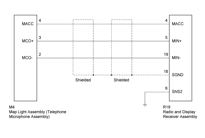
WIRING DIAGRAM
INSPECTION PROCEDURE
Tech Tips
For vehicles equipped with an Extension Module, refer to optional equipment's manuals.
PROCEDURE
-
CHECK MICROPHONE (OPERATION CHECK)
-
Enter the "Microphone & Voice Recognition Check" screen Click here.
-
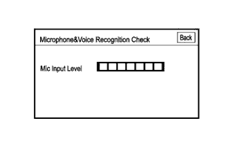
When voice is input into the microphone, check that the microphone input level meter changes according to the input voice.
OK Check result is normal.
NG 
CHECK HARNESS AND CONNECTOR (RADIO AND DISPLAY RECEIVER - MAP LIGHT) Click here
OK 
REPLACE RADIO AND DISPLAY RECEIVER ASSEMBLY Click here
-
-
CHECK HARNESS AND CONNECTOR (RADIO AND DISPLAY RECEIVER - MAP LIGHT)
-
Disconnect the R19 radio and display receiver assembly connector.
-
Disconnect the M4 map light assembly connector.
-
Measure the resistance according to the value(s) in the table below.
Standard Resistance Tester Connection Condition Specified Condition R19-4 (MACC) - M4-4 (MACC) Always Below 1 Ω R19-5 (MIN+) - M4-3 (MCO+) R19-19 (MIN-) - M4-2 (MCO-) R19-6 (SNS2) - Body ground R19-4 (MACC) - Body ground Always 10 kΩ or higher R19-5 (MIN+) - Body ground R19-19 (MIN-) - Body ground R19-18 (SGND) - Body ground
NG 
REPAIR OR REPLACE HARNESS OR CONNECTOR
OK 
-
-
CHECK RADIO AND DISPLAY RECEIVER ASSEMBLY
-
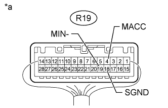
Text in Illustration *a Component with harness connected
(Radio and Display Receiver Assembly)
Measure the resistance according to the value(s) in the table below.
Standard Resistance Tester Connection Condition Specified Condition R19-18 (SGND) - Body ground Always Below 1 Ω R19-19 (MIN-) - Body ground -
Measure the voltage according to the value(s) in the table below.
Standard Voltage Tester Connection Switch Condition Specified Condition R19-4 (MACC) - Body ground Ignition switch ACC 4 to 6 V
NG
REPLACE RADIO AND DISPLAY RECEIVER ASSEMBLY Click here
OK
-
-
REPLACE TELEPHONE MICROPHONE WITH ANOTHER AND CHECK
-
Replace the telephone microphone with a normal one Click here.
-
Check if the same problem occurs again.
OK Malfunction disappears.
NG
REPLACE MAP LIGHT ASSEMBLY Click here
OK
END (TELEPHONE MICROPHONE ASSEMBLY IS DEFECTIVE)
-