METER / GAUGE SYSTEM Warning Buzzer does not Sound
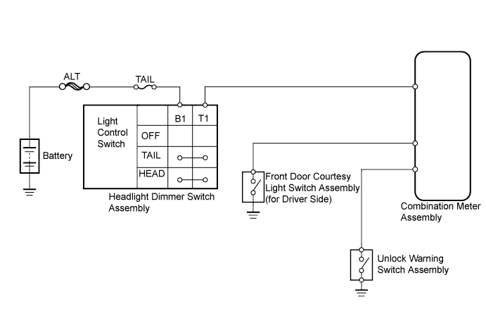
WIRING DIAGRAM
INSPECTION PROCEDURE
Note
Inspect the fuses for circuits related to this system before performing the following inspection procedure.
PROCEDURE
-
CHECK COMBINATION METER ASSEMBLY (BUZZER OPERATION)
-
Check the key reminder warning buzzer operation.
-
Turn the ignition switch OFF with the key inserted into the ignition key cylinder.
-
Open the driver side door.
OK Warning buzzer sounds.
-
-
Check the light reminder warning buzzer operation.
-
Turn the ignition switch OFF.
-
Set the light control switch to the TAIL or HEAD position.
-
Open the driver side door.
OK Warning buzzer sounds. Result Result Proceed to Key reminder warning buzzer does not sound A Light reminder warning buzzer does not sound B
-
B 
INSPECT HEADLIGHT DIMMER SWITCH ASSEMBLY (LIGHT CONTROL SWITCH) Click here
A 
-
-
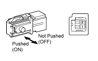
INSPECT UNLOCK WARNING SWITCH ASSEMBLY
-
Remove the unlock warning switch assembly.
-
Measure the resistance according to the value(s) in the table below.
Standard Resistance Tester Connection Switch Condition Specified Condition 1 - 2 Pushed (ON) Below 1 Ω 1 - 2 Not pushed (OFF) 10 kΩ or higher
NG 
REPLACE UNLOCK WARNING SWITCH ASSEMBLY
OK
-
-
CHECK HARNESS AND CONNECTOR (UNLOCK WARNING SWITCH - COMBINATION METER AND BODY GROUND)
-
Disconnect the U1 unlock warning switch assembly connector.
-
Disconnect the C27 combination meter assembly connector.
-
Measure the resistance according to the value(s) in the table below.
Standard Resistance Tester Connection Condition Specified Condition U1-1 - C27-10 (KSW) Always Below 1 Ω U1-2 - Body ground Always Below 1 Ω
OK
INSPECT FRONT DOOR COURTESY LIGHT SWITCH ASSEMBLY (FOR DRIVER SIDE) Click here
NG 
REPAIR OR REPLACE HARNESS OR CONNECTOR
-
-
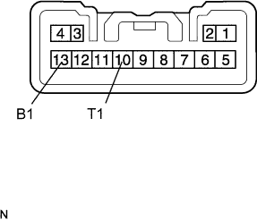
INSPECT HEADLIGHT DIMMER SWITCH ASSEMBLY (LIGHT CONTROL SWITCH)
-
Remove the headlight dimmer switch assembly.
-
Measure the resistance according to the value(s) in the table below.
Standard Resistance Tester Connection Switch Condition Specified Condition 13 (B1) - 10 (T1) HEAD Below 1 Ω 13 (B1) - 10 (T1) TAIL Below 1 Ω 13 (B1) - 10 (T1) OFF 10 kΩ or higher
NG
REPLACE HEADLIGHT DIMMER SWITCH ASSEMBLY
OK
-
-
CHECK HARNESS AND CONNECTOR (HEADLIGHT DIMMER SWITCH - COMBINATION METER AND BATTERY)
-
Disconnect the C12 headlight dimmer switch assembly connector.
-
Disconnect the C27 combination meter assembly connector.
-
Measure the voltage according to the value(s) in the table below.
Standard Voltage Tester Connection Condition Specified Condition C12-13 (B1) - Body ground Always 11 to 14 V -
Measure the resistance according to the value(s) in the table below.
Standard Resistance Tester Connection Condition Specified Condition C12-10 (T1) - C27-8 (ILL+) Always Below 1 Ω
NG
REPAIR OR REPLACE HARNESS OR CONNECTOR
OK
-
-
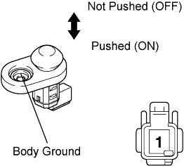
INSPECT FRONT DOOR COURTESY LIGHT SWITCH ASSEMBLY (FOR DRIVER SIDE)
-
Remove the front door courtesy light switch assembly (for Driver Side).
-
Measure the resistance according to the value(s) in the table below.
Standard Resistance Tester Connection Switch Condition Specified Condition 1 - Body ground Not pushed (OFF) Below 1 Ω 1 - Body ground Pushed (ON) 10 kΩ or higher
NG
REPLACE FRONT DOOR COURTESY LIGHT SWITCH ASSEMBLY (FOR DRIVER SIDE)
OK
-
-
CHECK HARNESS AND CONNECTOR (FRONT DOOR COURTESY LIGHT SWITCH - COMBINATION METER)
-
Disconnect the D4 front door courtesy light switch assembly (for Driver Side) connector.
-
Disconnect the C27 combination meter assembly connector.
-
Measure the resistance according to the value(s) in the table below.
Standard Resistance Tester Connection Condition Specified Condition D4-1 - C27-16 (DCTY) Always Below 1 Ω
NG
REPAIR OR REPLACE HARNESS OR CONNECTOR
OK
REPLACE COMBINATION METER ASSEMBLY Click here
-