METER / GAUGE SYSTEM Fuel Receiver Gauge Malfunction
DESCRIPTION
-
The fuel sender gauge has a variable resistance mechanism. The resistance decreases when the fuel amount increases, and the resistance increases when the fuel amount decreases. The fuel receiver gauge changes based on the resistance of the fuel sender gauge.
Note
When the combination meter is removed or replaced, its connector is disconnected or fuel is added, the fuel receiver gauge display will return to normal within a maximum of 16 minutes after the ignition switch is turned to ON or when vehicle speed is input.
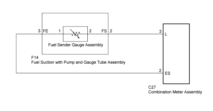
WIRING DIAGRAM
INSPECTION PROCEDURE
PROCEDURE
-
CHECK HARNESS AND CONNECTOR (COMBINATION METER ASSEMBLY - FUEL SUCTION WITH PUMP AND GAUGE TUBE ASSEMBLY)
-
Disconnect the C27 combination meter assembly connector.
-
Disconnect the F14 fuel suction with pump and gauge tube assembly connector.
-
Measure the resistance according to the value(s) in the table below.
Standard Resistance Tester Connection Condition Specified Condition C27-2 (ES) - F14-3 (FE) Always Below 1 Ω C27-3 (L) - F14-2 (FS) Always Below 1 Ω C27-2 (ES) - C27-3 (L) Always 10 kΩ or higher C27-2 (ES) - Body ground Always 10 kΩ or higher C27-3 (L) - Body ground Always 10 kΩ or higher
NG 
REPAIR OR REPLACE HARNESS OR CONNECTOR
OK 
-
-
INSPECT FUEL SUCTION WITH PUMP AND GAUGE TUBE ASSEMBLY
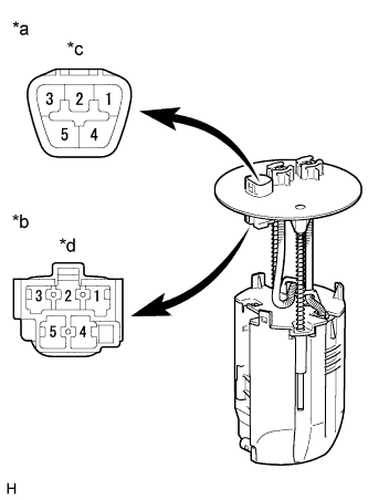
Text in Illustration *a Upper Side *b Lower Side
(to Fuel Sender Gauge Assembly)
*c Connector A *d Connector B
-
Remove the fuel suction with pump and gauge assembly .
-
Measure the resistance according to the value(s) in the table below.
Standard Resistance Tester Connection Condition Specified Condition A-2 - B-2 Always Below 1 Ω A-3 - B-1 Always Below 1 Ω A-2 - A-3 Always 10 kΩ or higher
NG
REPLACE FUEL SUCTION WITH PUMP AND GAUGE TUBE ASSEMBLY
OK
-
-
INSPECT FUEL SENDER GAUGE ASSEMBLY
-
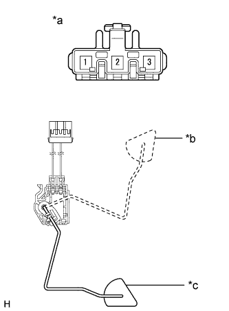
Text in Illustration *a Front view of wire harness connector
(to Fuel Sender Gauge Assembly)
*b Float Position F (Upper) *c Float Position E (Lower) Remove the fuel sender gauge assembly.
-
Measure the resistance according to the value(s) in the table below.
Standard Resistance Tester Connection Condition Specified Condition 1 - 2 Float position F (upper) 3 to 5 Ω Float position E (lower) 109 to 111 Ω
NG
REPLACE FUEL SENDER GAUGE ASSEMBLY
OK 
REPLACE COMBINATION METER ASSEMBLY Click here
-