WIRELESS DOOR LOCK CONTROL SYSTEM (for Non-built-in Type Door Control Receiver) Only Wireless Control Function is Inoperative
DESCRIPTION
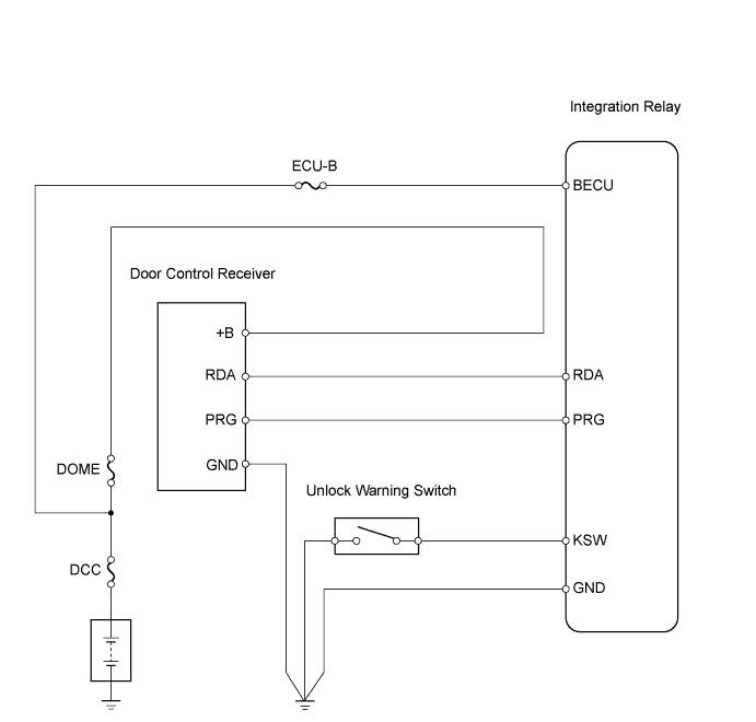
The door control receiver receives signals from the transmitter and sends these signals to the instrument panel junction block (integration relay). The instrument panel junction block (integration relay) then controls all doors by sending lock / unlock signals to each door and hazard flasher relay signals to the turn signal flasher relay (hazard warning lights).
WIRING DIAGRAM
INSPECTION PROCEDURE
PROCEDURE
-
CHECK WIRELESS DOOR LOCK CONTROL FUNCTIONS
OK Each function of wireless door lock control system operates normally using transmitter switches (see page Click here).
OK 
END
NG 
-
CHECK THAT TRANSMITTER LED ILLUMINATES
-
Check that the transmitter's LED illuminates 3 times when the switch is pressed 3 times.
OK Transmitter's LED illuminates 3 times when switch is pressed 3 times.
NG 
REPLACE TRANSMITTER BATTERY Click here
OK
-
-
CHECK WIRELESS DOOR LOCK CONTROL FUNCTION (STANDARD OPERATION FUNCTION)
Tech Tips
Use the following standardized test procedure to check the transmitter again.
-
Hold the transmitter approximately 1 m (3.28 ft.) from the driver side door outside handle. The transmitter must be parallel to the ground and perpendicular to the side of the vehicle.
-
Press and hold either the LOCK or UNLOCK transmitter switch for 1 second, and check that the doors lock or unlock, respectively.
OK Doors can be locked and unlocked with transmitter switches (see page Click here).
NG
CHECK ROOM NO. 1 LIGHT ASSEMBLY Click here
OK 
REPLACE DOOR CONTROL TRANSMITTER MODULE
-
-
REPLACE TRANSMITTER BATTERY
-
After replacing the transmitter battery Click here, check that the doors can be locked and unlocked using the transmitter switches.
OK Doors can be locked and unlocked with transmitter (see page Click here).
NG
REPLACE DOOR CONTROL TRANSMITTER MODULE
OK
END (TRANSMITTER BATTERY DEFECTIVE)
-
-
CHECK ROOM NO. 1 LIGHT ASSEMBLY
-
Check that the room No. 1 light illumination operates normally.
OK Room No. 1 light illumination operates normally.
NG
GO TO LIGHTING SYSTEM
OK
-
-
SWITCH TO SELF-DIAGNOSTIC MODE
-
Switch to self-diagnostic mode by operating the ignition key cylinder.
-
Make sure the vehicle is in its initial condition Click here. Then insert the key into the ignition key cylinder and remove it.
-
Within 5 seconds of removing the key, insert the key into the ignition key cylinder (ignition switch OFF). Then turn the ignition switch ON and OFF.
-
Within 30 seconds of turning the ignition switch OFF, perform the following 9 times: turn the ignition switch ON and OFF.
Note
If the change to self-diagnostic mode has failed, the system will return to normal mode.
Tech Tips
-
Turning the ignition switch ON after the above operations have been completed will end self-diagnostic mode.
-
Do not lock or unlock doors during self-diagnostic mode.
-
-
-
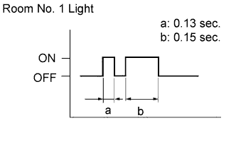
Check that the system has switched to self-diagnostic mode by checking the room No. 1 light flash pattern.
OK Flash pattern should be same as illustration.
NG
CONFIRM INPUT METHOD OF SELF-DIAGNOSTIC MODE Click here
OK
-
-
CHECK BY SELF-DIAGNOSTIC MODE
-
Inspect the diagnosis outputs when the door control transmitter switch is held down. The diagnosis outputs can be checked by the flash patterns of the room No. 1 light.
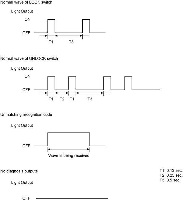
Result: Result Proceed to Unmatching recognition code is output A Normal waves (light flash patterns) for LOCK and UNLOCK switches are output B No diagnosis outputs are present C
B
REPLACE INSTRUMENT PANEL JUNCTION BLOCK
C
CHECK RESPONSE OF DOOR CONTROL RECEIVER Click here
A
-
-
REGISTER RECOGNITION CODE
-
Check that the system can be switched to rewrite mode or add mode, and that a recognition code can be registered.
OK Recognition code can be registered.
NG
REPLACE DOOR CONTROL TRANSMITTER MODULE Click here
OK
END
-
-
CHECK RESPONSE OF DOOR CONTROL RECEIVER
-
When a new or normally functioning door lock control transmitter switch for the same type vehicle is held down, check that an unmatching recognition code is output.
OK Unmatching recognition code is output.
OK
REPLACE DOOR CONTROL TRANSMITTER MODULE
NG
-
-
REPLACE DOOR CONTROL RECEIVER
-
After replacing the door control receiver Click here, check that the doors can be locked and unlocked by using the transmitter LOCK / UNLOCK switch.
OK Doors can be locked and unlocked with transmitter.
NG
REPLACE INSTRUMENT PANEL JUNCTION BLOCK
OK
END
-
-
CONFIRM INPUT METHOD OF SELF-DIAGNOSTIC MODE
-
When the input method for switching the system to self-diagnostic mode is correct, proceed to A.
-
When the input method for switching the system to self-diagnostic mode is incorrect, proceed to B.
B
SWITCH TO SELF-DIAGNOSTIC MODE Click here
A
-
-
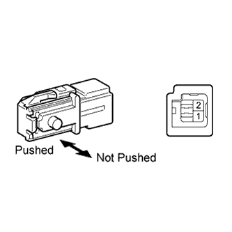
INSPECT UNLOCK WARNING SWITCH ASSEMBLY
-
Remove the switch.
-
Measure the resistance of the switch.
Standard resistance Tester Connection Switch Condition Specified Condition 1 - 2 Not pushed 10 kΩ or higher Pushed Below 1 Ω
NG
REPLACE UNLOCK WARNING SWITCH ASSEMBLY
OK
-
-
CHECK WIRE HARNESS (DOOR CONTROL RECEIVER - INTEGRATION RELAY)
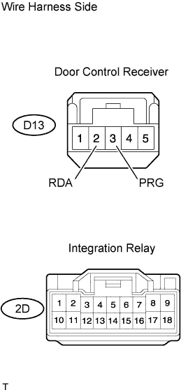
-
Disconnect the D13 receiver connector.
-
Disconnect the 2D junction block connector.
-
Measure the resistance of the wire harness side connectors.
Standard resistance Tester Connection Specified Condition D13-3 (PRG) - 2D-2 Below 1 Ω D13-2 (RDA) - 2D-5 Below 1 Ω
NG
REPAIR OR REPLACE HARNESS AND CONNECTOR
OK
-
-
CHECK DOOR CONTROL RECEIVER (OUTPUT)
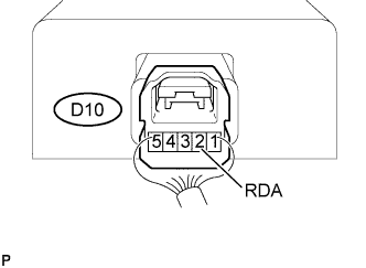
-
Reconnect the D13 receiver connector.
-
Measure the resistance of the connector.
Standard voltage Tester Connection Condition Specified Condition D13-2 (RDA) - Body ground Transmitter switch ON → OFF (No key in ignition key cylinder, all doors closed) Below 1 V →
6 to 7 V →
Below 1 V
OK
REPLACE INSTRUMENT PANEL JUNCTION BLOCK
NG
-
-
REPLACE DOOR CONTROL TRANSMITTER MODULE
-
Check that the doors can be locked and unlocked by using the transmitter LOCK / UNLOCK switch.
OK Doors can be locked and unlocked with transmitter.
NG
REPLACE DOOR CONTROL RECEIVER
OK
END (DOOR CONTROL TRANSMITTER MODULE IS DEFECTIVE)
-