WIRELESS DOOR LOCK CONTROL SYSTEM (for Built-in Type Door Control Receiver) Only Wireless Control Function is Inoperative
DESCRIPTION
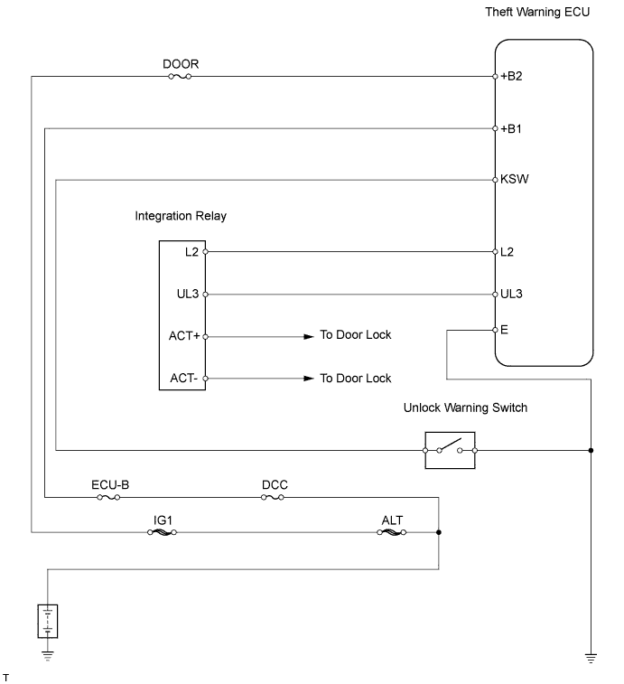
The theft warning ECU assembly receives a signal from the transmitter. The theft warning ECU assembly then controls all doors by sending all of the following: 1) lock / unlock signals to each door, 2) hazard flasher relay signals to the turn signal flasher relay (hazard warning lights), 3) security horn signals to the security horn*.
Tech Tips
*: The security horn applies only if the wireless answer-back function has been customized so that the hazard warning lights flash and the security horn sounds.
WIRING DIAGRAM
INSPECTION PROCEDURE
PROCEDURE
-
CHECK WIRELESS DOOR LOCK CONTROL FUNCTIONS
OK Each function of wireless door lock control system operates normally using transmitter switches (see page Click here).
OK 
END
NG 
-
CHECK THAT TRANSMITTER LED ILLUMINATES
-
Check that the transmitter's LED illuminates 3 times when the switch is pressed 3 times.
OK Transmitter's LED illuminates 3 times when switch is pressed 3 times.
NG 
CHECK WIRELESS DOOR LOCK CONTROL FUNCTION (STANDARD OPERATION FUNCTION) Click here
OK
-
-
REPLACE TRANSMITTER BATTERY
-
After replacing the transmitter battery Click here, check that the doors can be locked and unlocked using the transmitter switches.
OK Doors can be locked and unlocked with transmitter (see page Click here).
NG
REPLACE DOOR CONTROL TRANSMITTER MODULE
OK 
END (DOOR CONTROL TRANSMITTER MODULE IS DEFECTIVE)
-
-
CHECK WIRELESS DOOR LOCK CONTROL FUNCTION (STANDARD OPERATION FUNCTION)
Tech Tips
Use the following standardized test procedure to check the transmitter again.
-
Hold the transmitter approximately 1 m (3.28 ft.) from the driver side door outside handle. The transmitter must be parallel to the ground and perpendicular to the side of the vehicle.
-
Press and hold either the LOCK or UNLOCK transmitter switch for 1 second, and check that the doors lock or unlock, respectively.
OK Doors can be locked and unlocked with transmitter switches (see page Click here).
NG
INSPECT FUSE (ECU-B, DCC, DOOR) Click here
OK
END
-
-
INSPECT FUSE (ECU-B, DCC, DOOR)
-
Remove the ECU-B and DCC fuses from the engine room relay block.
-
Remove the DOOR fuse from the No. 3 relay block.
-
Measure the resistance of the fuses.
Standard resistance Below 1 Ω
NG
REPLACE FUSE
OK
-
-
INSPECT UNLOCK WARNING SWITCH ASSEMBLY
-
Remove the switch.
-
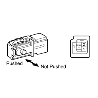
Measure the resistance of the switch.
Standard resistance Tester Connection Condition Specified Condition 1 - 2 Not pushed 10 kΩ or higher Pushed Below 1 Ω
NG
REPLACE UNLOCK WARNING SWITCH ASSEMBLY
OK
-
-
CHECK WIRE HARNESS (UNLOCK WARNING SWITCH - THEFT WARNING ECU AND BODY GROUND)
-
Disconnect the U1 switch connector.
-
Disconnect the T16 ECU connector.
-
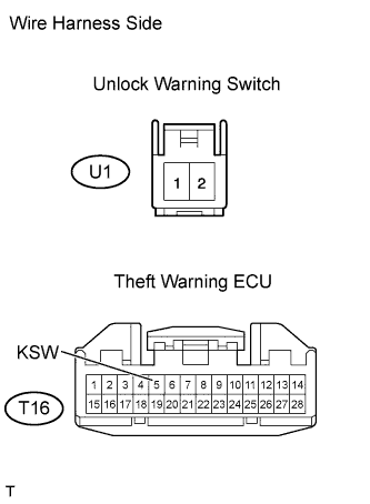
Measure the resistance of the wire harness side connectors.
Standard resistance Tester Connection Specified Condition U1-1 - T16-5 (KSW) Below 1 Ω U1-2 - Body ground
NG
REPAIR OR REPLACE HARNESS AND CONNECTOR
OK
-
-
REGISTER RECOGNITION CODE
-
Check that the system can be switched to rewrite mode or add mode, and that a recognition code can be registered.
OK Recognition code can be registered.
OK
END
NG
-
-
CHECK WIRE HARNESS (THEFT WARNING ECU - INTEGRATION RELAY)
-
Disconnect the T16 ECU connector.
-
Disconnect the 2A and 2D junction block connectors.
-
Measure the resistance of the wire harness side connectors.
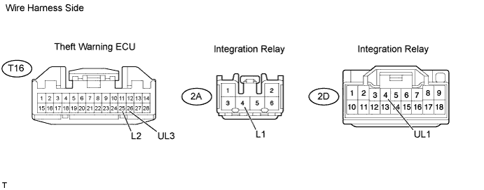
Standard resistance Tester Connection Specified Condition T16-25 (L2) - 2A-4 (L1) Below 1 Ω T16-26 (UL3) - 2D-4 (UL1)
NG
REPAIR OR REPLACE HARNESS AND CONNECTOR
OK
-
-
CHECK WIRE HARNESS (THEFT WARNING ECU - BATTERY AND BODY GROUND)
-
Disconnect the T16 ECU connector.
-
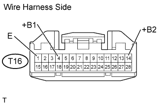
Measure the resistance and voltage of the wire harness side connector.
Standard resistance Tester Connection Specified Condition T16-1 (E) - Body ground Below 1 Ω Standard voltage Tester Connection Specified Condition T16-4 (+B1) - Body ground 10 to 14 V T16-14 (+B2) - Body ground
NG
REPAIR OR REPLACE HARNESS AND CONNECTOR
OK
REPLACE THEFT WARNING ECU ASSEMBLY
-