POWER DOOR LOCK CONTROL SYSTEM All Doors cannot be Locked / Unlocked Simultaneously
DESCRIPTION
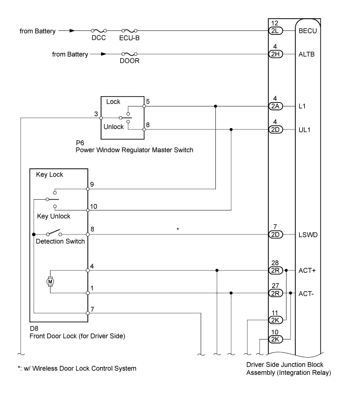
The integration relay drives the door lock motors according to switch signals from the door control switch of the power window regulator master switch and the driver side door key cylinder.
However, the driver side door key-linked lock / unlock function will not operate when the seat belt is fastened.
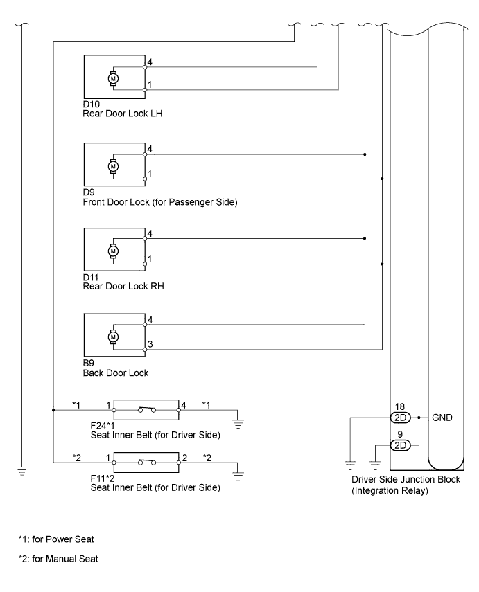
WIRING DIAGRAM
INSPECTION PROCEDURE
PROCEDURE
-
CHECK DOOR LOCK / UNLOCK OPERATION
-
Proceed to the next step according to the system listed in the table below.
Symptom Proceed to All doors cannot be locked / unlocked at once using door control switch on master switch (switch operation) A All doors cannot be locked / unlocked at once using door key cylinder on driver side (key operation) B Only one door cannot be locked / unlocked C All symptoms listed above are present D
B 
INSPECT FRONT DOOR LOCK (DRIVER SIDE DOOR LOCK AND UNLOCK SWITCH) Click here
C
INSPECT DOOR LOCK (DRIVER SIDE, PASSENGER SIDE, REAR LH, REAR RH AND BACK DOOR) Click here
D
INSPECT FUSE (ECU-B, DCC, DOOR) Click here
A 
-
-
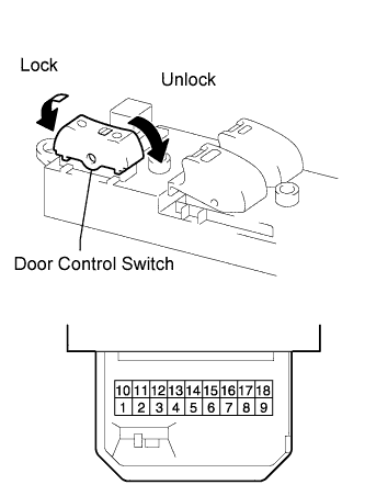
INSPECT POWER WINDOW REGULATOR MASTER SWITCH (DOOR CONTROL SWITCH)
-
Measure the resistance of the door control switch.
Standard resistance Tester Connection Switch Condition Specified Condition 5 - 3 Lock Below 1 Ω 5 - 3, 8- 3 OFF 10 kΩ or higher 8 - 3 Unlock Below 1 Ω
NG 
REPLACE POWER WINDOW REGULATOR MASTER SWITCH
OK
-
-
CHECK WIRE HARNESS (MASTER SWITCH - INTEGRATION RELAY AND BODY GROUND)
-
Disconnect the P6 switch connector.
-
Disconnect the 2A and 2D integration relay connectors.
-
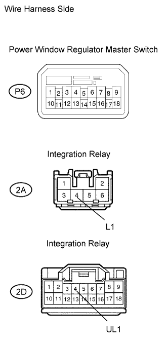
Measure the resistance of the wire harness side connectors.
Standard resistance Tester Connection Specified Condition P6-5 - 2A-4 (L1) Below 1 Ω P6-8 - 2D-4 (UL1) Below 1 Ω P6-3 - Body ground Below 1 Ω P6-5 or 2A-4 (L1) - Body ground 10 kΩ or higher P6-8 or 2D-4 (UL1) - Body ground 10 kΩ or higher
NG
REPAIR OR REPLACE HARNESS AND CONNECTOR
OK 
REPLACE DRIVER SIDE JUNCTION BLOCK ASSEMBLY
-
-
INSPECT FRONT DOOR LOCK (DRIVER SIDE DOOR LOCK AND UNLOCK SWITCH)
-
w/ Wireless Door Lock Control System:
-
Measure the resistance of the door lock and unlock switch.
Standard resistance Tester Connection Door Lock Condition Specified Condition 7 - 9 Lock Below 1 Ω 7 - 9, 7 - 10 OFF 10 kΩ or higher 7 - 10 Unlock Below 1 Ω -
Measure the resistance of the detection switch.
Standard resistance Tester Connection Door Lock Condition Specified Condition 7 - 8 Lock 10 kΩ or higher 7 - 8 Unlock Below 1 Ω
-
-
w/o Wireless Door Lock Control System:
-
Measure the resistance of the door lock and unlock switch.
Standard resistance Tester Connection Door Lock Condition Specified Condition 7 - 9 Lock Below 1 Ω 7 - 9, 7 - 10 OFF 10 kΩ or higher 7 - 10 Unlock Below 1 Ω
-
NG
REPLACE FRONT DOOR LOCK (DRIVER SIDE)
OK
-
-
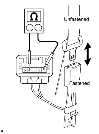
INSPECT FRONT SEAT INNER BELT (FOR DRIVER SIDE)
-
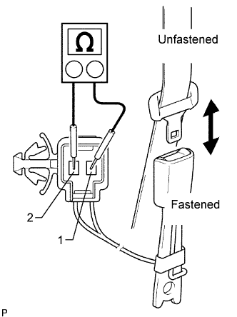
for Power Seat:
Measure the resistance of the buckle switch.
Standard resistance Tester Connection Switch Condition Specified Condition 1 - 4 Seat belt is unfastened Below 1 Ω 1 - 4 Seat belt is fastened 1 MΩ or higher -
for Manual Seat:
Measure the resistance of the buckle switch.
Standard resistance Tester Connection Switch Condition Specified Condition 1 - 2 Seat belt is unfastened Below 1 Ω 1 - 2 Seat belt is fastened 1 MΩ or higher
NG
REPLACE FRONT SEAT INNER BELT (FOR DRIVER SIDE)
OK
-
-
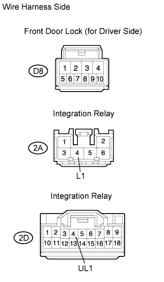
CHECK WIRE HARNESS (DRIVER SIDE DOOR LOCK - INTEGRATION RELAY AND BODY GROUND)
-
Disconnect the D8 door lock connector.
-
Disconnect the 2A and 2D integration relay connectors.
-
Measure the resistance of the wire harness side connectors.
Standard resistance Tester Connection Condition Specified Condition D8-10 - 2D-4 (UL1) Always Below 1 Ω D8-9 - 2A-4 (L1) Always Below 1 Ω D8-7 - Body ground Driver seat belt is unfastened Below 1 Ω D8-8 - 2D-7 (LSWD)* Always Below 1 Ω D8-10 or 2D-4 (UL1) - Body ground Always 10 kΩ or higher D8-9 or 2A-4 (L1) - Body ground Always 10 kΩ or higher D8-8 or 2D-7 (LSWD) - Body ground* Always 10 kΩ or higher *: w/ Wireless Door Lock Control System
NG
REPAIR OR REPLACE HARNESS AND CONNECTOR
OK
REPLACE DRIVER SIDE JUNCTION BLOCK ASSEMBLY
-
-
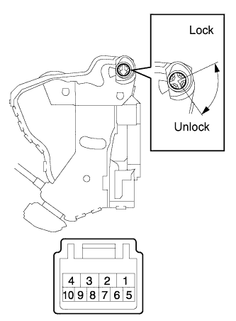
INSPECT DOOR LOCK (DRIVER SIDE, PASSENGER SIDE, REAR LH, REAR RH AND BACK DOOR)
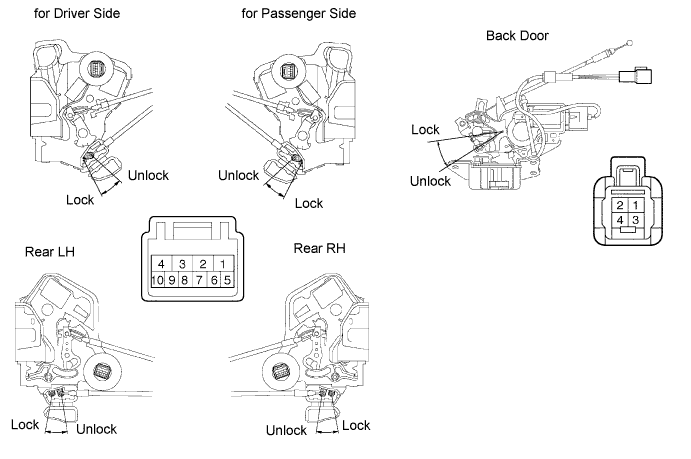
-
Apply battery voltage to the door lock and check the operation of the door lock motor.
OK Driver side, Passenger side, Rear LH, Rear RH Measurement Condition Specified Condition Battery positive (+) → Terminal 4
Battery negative (-) → Terminal 1
Lock Battery positive (+) → Terminal 1
Battery negative (-) → Terminal 4
Unlock Back door Measurement Condition Specified Condition Battery positive (+) → Terminal 4
Battery negative (-) → Terminal 3
Lock Battery positive (+) → Terminal 3
Battery negative (-) → Terminal 4
Unlock
NG
REPLACE DOOR LOCK
OK
-
-
CHECK WIRE HARNESS (DOOR LOCK - INTEGRATION RELAY AND BODY GROUND)
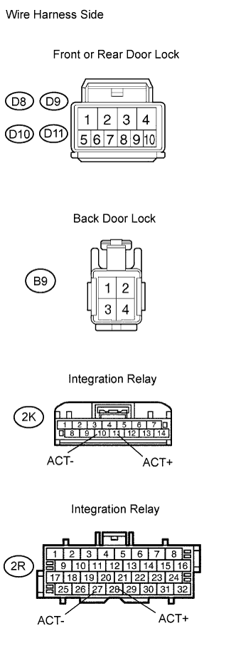
-
Disconnect the D8, D9, D10 and D11 door lock connectors.
-
Disconnect the B9 back door lock connector.
-
Disconnect the 2K and 2R integration relay connectors.
-
Measure the resistance of the wire harness side connectors.
Standard resistance Tester Connection Specified Condition D8-4 - 2R-28 (ACT+) Below 1 Ω D8-1 - 2R-27 (ACT-) Below 1 Ω D9-4 - 2K-11 (ACT+) Below 1 Ω D9-1 - 2K-10 (ACT-) Below 1 Ω D10-4 - 2R-28 (ACT+) Below 1 Ω D10-1 - 2R-27 (ACT-) Below 1 Ω D11-4 - 2K-11 (ACT+) Below 1 Ω D11-1 - 2K-10 (ACT-) Below 1 Ω B9-4 - 2K-11 (ACT+) Below 1 Ω B9-3 - 2K-10 (ACT-) Below 1 Ω D8-4 or 2R-28 (ACT+) - Body ground 10 kΩ or higher D8-1 or 2R-27 (ACT-) - Body ground 10 kΩ or higher D9-4 or 2K-11 (ACT+) - Body ground 10 kΩ or higher D9-1 or 2K-10 (ACT-) - Body ground 10 kΩ or higher D10-4 or 2R-28 (ACT+) - Body ground 10 kΩ or higher D10-1 or 2R-27 (ACT-) - Body ground 10 kΩ or higher D11-4 or 2K-11 (ACT+) - Body ground 10 kΩ or higher D11-1 or 2K-10 (ACT-) - Body ground 10 kΩ or higher B9-4 or 2K-11 (ACT+) - Body ground 10 kΩ or higher B9-3 or 2K-10 (ACT-) - Body ground 10 kΩ or higher
NG
REPAIR OR REPLACE HARNESS AND CONNECTOR
OK
REPLACE DRIVER SIDE JUNCTION BLOCK ASSEMBLY
-
-
INSPECT FUSE (ECU-B, DCC, DOOR)
-
Remove the ECU-B and DCC fuses from the engine room relay block.
-
Remove the DOOR fuse from the No. 3 relay block.
-
Measure the resistance of the fuses.
Standard resistance Below 1 Ω
NG
REPLACE FUSE
OK
-
-
CHECK WIRE HARNESS (INTEGRATION RELAY - BATTERY AND BODY GROUND)
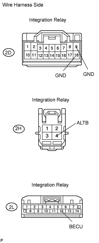
-
Disconnect the 2D, 2H and 2L integration relay connectors.
-
Measure the voltage and resistance of the wire harness side connectors.
Standard voltage Tester Connection Specified Condition 2L-12 (BECU) - Body ground 11 to 14 V 2H-4 (ALTB) - Body ground 11 to 14 V Standard resistance Tester Connection Specified Condition 2D-9 (GND) - Body ground Below 1 Ω 2D-18 (GND) - Body ground Below 1 Ω
NG
REPAIR OR REPLACE HARNESS AND CONNECTOR
OK
-
-
CHECK WIRE HARNESS (MASTER SWITCH - INTEGRATION RELAY AND BODY GROUND)
-
Disconnect the P6 switch connector.
-
Disconnect the 2A and 2D integration relay connectors.
-
Measure the resistance of the wire harness side connectors.
Standard resistance Tester Connection Specified Condition P6-5 - 2A-4 (L1) Below 1 Ω P6-8 - 2D-4 (UL1) Below 1 Ω P6-3 - Body ground Below 1 Ω P6-5 or 2A-4 (L1) - Body ground 10 kΩ or higher P6-8 or 2D-4 (UL1) - Body ground 10 kΩ or higher
NG
REPAIR OR REPLACE HARNESS AND CONNECTOR
OK
REPLACE DRIVER SIDE JUNCTION BLOCK ASSEMBLY
-