POWER DOOR LOCK CONTROL SYSTEM TERMINALS OF ECU

-
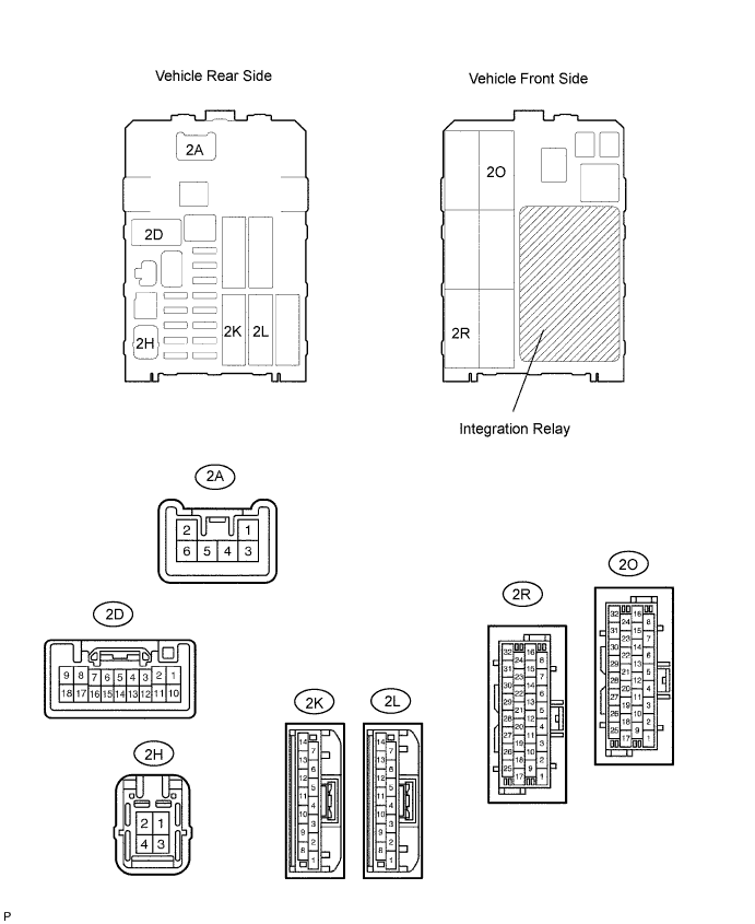
CHECK DRIVER SIDE JUNCTION BLOCK (INTEGRATION RELAY)
-
Disconnect the 2A, 2D, 2H and 2L junction block connectors.
-
Measure the voltage and resistance of the wire harness side connector.
Symbols (Terminal No.) Wiring Color Terminal Description Condition Specified Condition BECU (2L-12) - Body ground L - Body ground +B (BECU) power supply Always 10 to 14 V ALTB (2H-4) - Body ground LG - Body ground +B (power system, generator system) power supply Always 10 to 14 V GND (2D-9, 18) - Body ground W-B - Body ground Ground Always Below 1 Ω L1 (2A-4) - Body ground L - Body ground Door control switch lock input Door control switch OFF 10 kΩ or higher L1 (2A-4) - Body ground L - Body ground Door control switch lock input Door control switch LOCK Below 1 Ω UL1 (2D-4) - Body ground L-W - Body ground Door control switch unlock input Door control switch OFF 10 kΩ or higher UL1 (2D-4) - Body ground L-W - Body ground Door control switch unlock input Door control switch UNLOCK Below 1 Ω
-
If the result is not as specified, there may be a malfunction on the wire harness side.
-
-
Reconnect the 2A, 2D, 2H and 2L junction block connectors.
-
Measure the voltage of the connectors.
Symbols (Terminal No.) Wiring Color Terminal Description Condition Specified Condition ACT+ (2R-28) - Body ground L - Body ground Door lock motor LOCK drive output (driver door and rear LH door) Door control switch or driver door key cylinder OFF Below 1 V ACT+ (2R-28) - Body ground L - Body ground Door lock motor LOCK drive output (driver door and rear LH door) Door control switch or driver door key cylinder LOCK 10 to 14 V ACT+ (2K-11) - Body ground L - Body ground Door lock motor LOCK drive output (passenger door, rear RH door and back door) Door control switch or driver door key cylinder OFF Below 1 V ACT+ (2K-11) - Body ground L - Body ground Door lock motor LOCK drive output (passenger door, rear RH door and back door) Door control switch or driver door key cylinder LOCK 10 to 14 V ACT- (2R-27) - Body ground L-Y - Body ground Door lock motor UNLOCK drive output (driver door and rear LH door) Door control switch or driver door key cylinder OFF Below 1 V ACT- (2R-27) - Body ground L-Y - Body ground Door lock motor UNLOCK drive output (driver door and rear LH door) Door control switch or driver door key cylinder UNLOCK 10 to 14 V ACT- (2K-10) - Body ground L-Y - Body ground Door lock motor UNLOCK drive output (passenger door, rear RH door and back door) Door control switch or driver door key cylinder OFF Below 1 V ACT- (2K-10) - Body ground L-Y - Body ground Door lock motor UNLOCK drive output (passenger door, rear RH door and back door) Door control switch or driver door key cylinder UNLOCK 10 to 14 V DCTY (2O-27) - Body ground R-B - Body ground Driver side courtesy switch input Driver side door closed Below 1 V DCTY (2O-27) - Body ground R-B - Body ground Driver side courtesy switch input Driver side door open 10 to 14 V
-
If the result is not as specified, the junction block relay (integration relay) may have a malfunction.
-