METER / GAUGE SYSTEM ON-VEHICLE INSPECTION

-
CHECK SPEEDOMETER
-
Check operation.
-
Connect the intelligent tester to the DLC3.
-
Turn the ignition switch to ON.
-
Turn the intelligent tester on.
-
Enter the following menus: Powertrain / Engine and ECT / Data List.
Reference Standard Indication Acceptable Range 20 km/h 21 to 25 km/h 40 km/h 41.7 to 46.2 km/h 60 km/h 62.7 to 67.2 km/h 80 km/h 83.4 to 88.4 km/h 100 km/h 104.3 to 109.3 km/h 120 km/h 125.1 to 130.6 km/h 140 km/h 145.8 to 151.8 km/h 160 km/h 166.2 to 173.2 km/h 180 km/h 186.9 to 194.5 km/h Note
Do not use worn, underinflated or overinflated tires, as the speedometer reading will be inaccurate.
-
Check the deflection width of the speedometer indicator.
Reference Within 0.3° If the result is not as specified, the speedometer may have a malfunction.
-
-
-
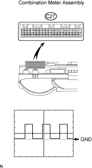
CHECK OUTPUT SIGNAL OF VEHICLE SPEED SENSOR
-
Check the output signal waveform.
-
Remove the combination meter, but do not disconnect the connector.
-
Using an oscilloscope, check the waveform of the combination meter.
Item Content Tester Connection C27-6 - C27-22 Tool Setting 5 V/DIV., 20 msec./DIV. Vehicle Condition Vehicle running OK Refer to the illustration. Tech Tips
-
As vehicle speed increases, the wavelength shortens.
-
If the result is not specified, the speedometer may have a malfunction.
-
-
-
-
CHECK TACHOMETER
-
Check operation.
-
Connect the intelligent tester to the DLC3.
-
Turn the ignition switch to ON.
-
Turn the intelligent tester on.
-
Enter the following menus: Powertrain / Engine and ECT / Data List.
-
Compare the test tachometer values and vehicle tachometer values under the following conditions:
-
Vehicle battery voltage is 13.5 V
-
Ambient temperature is 25°C (77°F)
OK Standard Tachometer Indication (rpm) Acceptable Range (rpm)
Data in ( ) are for reference only
700 630 to 770 1000 (900 to 1100) 2000 (1850 to 2150) 3000 2800 to 3200 4000 (3800 to 4200) 5000 4800 to 5200 6000 (5750 to 6250) 7000 6700 to 7300 If the result is not as specified, the tachometer may have a malfunction.
-
-
-
-
CHECK FUEL SUCTION WITH PUMP AND GAUGE TUBE ASSEMBLY
-
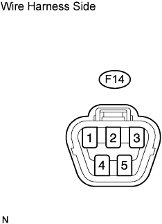
Disconnect the F14 pump and gauge connector.
-
Turn the ignition switch ON, and then check the position of the receiver gauge needle.
OK Fuel receiver gauge indicates E. -
Connect terminals 2 and 3 of the wire harness side connector.
-
Turn the ignition switch ON, and then check the position of the receiver gauge needle.
OK Fuel receiver gauge indicates F. If the result is not as specified, the combination meter may have a malfunction.
-
-
CHECK FUEL LEVEL WARNING LIGHT
-
Disconnect the F14 pump and gauge connector.
-
Turn the ignition switch ON, and then check that the fuel receiver gauge indicates E and that the fuel level warning light turns on.
OK Fuel level warning light turns on. If the result is not as specified, the combination meter may have a malfunction.
-
-
CHECK LOW OIL PRESSURE WARNING LIGHT
-
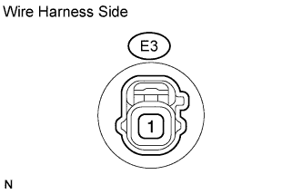
Disconnect the E3 switch connector.
-
Connect terminal 1 of the wire harness side connector to the body ground.
-
Turn the ignition switch ON, and then check that the low oil pressure warning light turns on.
OK Low oil pressure warning light turns on. If the result is not as specified, the combination meter may have a malfunction.
-
-
CHECK BRAKE WARNING LIGHT
-
Check the parking brake warning light.
-
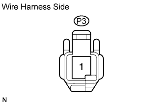
Disconnect the P3 switch connector.
-
Connect terminal 1 of the wire harness side connector to the body ground.
-
Turn the ignition switch ON, and then check that the warning light turns on.
OK Warning light turns on.
-
-
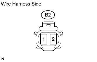
Check the brake fluid level warning light.
-
Disconnect the B2 switch connector.
-
Connect terminals 1 and 2 of the wire harness side connector.
-
Turn the ignition switch ON, and then check that the warning light turns on.
OK Warning light turns on.
-
-
-
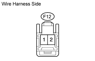
CHECK SEAT BELT WARNING LIGHT FOR PASSENGER SIDE
-
Disconnect the F12 switch connector.
-
Connect terminals 1 and 2 of the wire harness side connector.
-
Turn the ignition switch ON, and then check that the warning light blinks.
OK Seat belt warning light for passenger side blinks. If the result is not as specified, the accessory meter (multi-display)*1 or passenger seat belt warning light*2 may have a malfunction.
Tech Tips
*1: w/ Accessory meter
*2: w/o Accessory meter
-